This thread has been locked.

If you have a related question, please click the "Ask a related question" button in the top right corner. The newly created question will be automatically linked to this question.

UC3845: Current sens resistor calculation when extra fading voltage from Vref pin

Part Number: UC3845

Hi;

I am making Constant voltage 5VDC flyback based power supply using UC3845. I have read TI datasheet .  

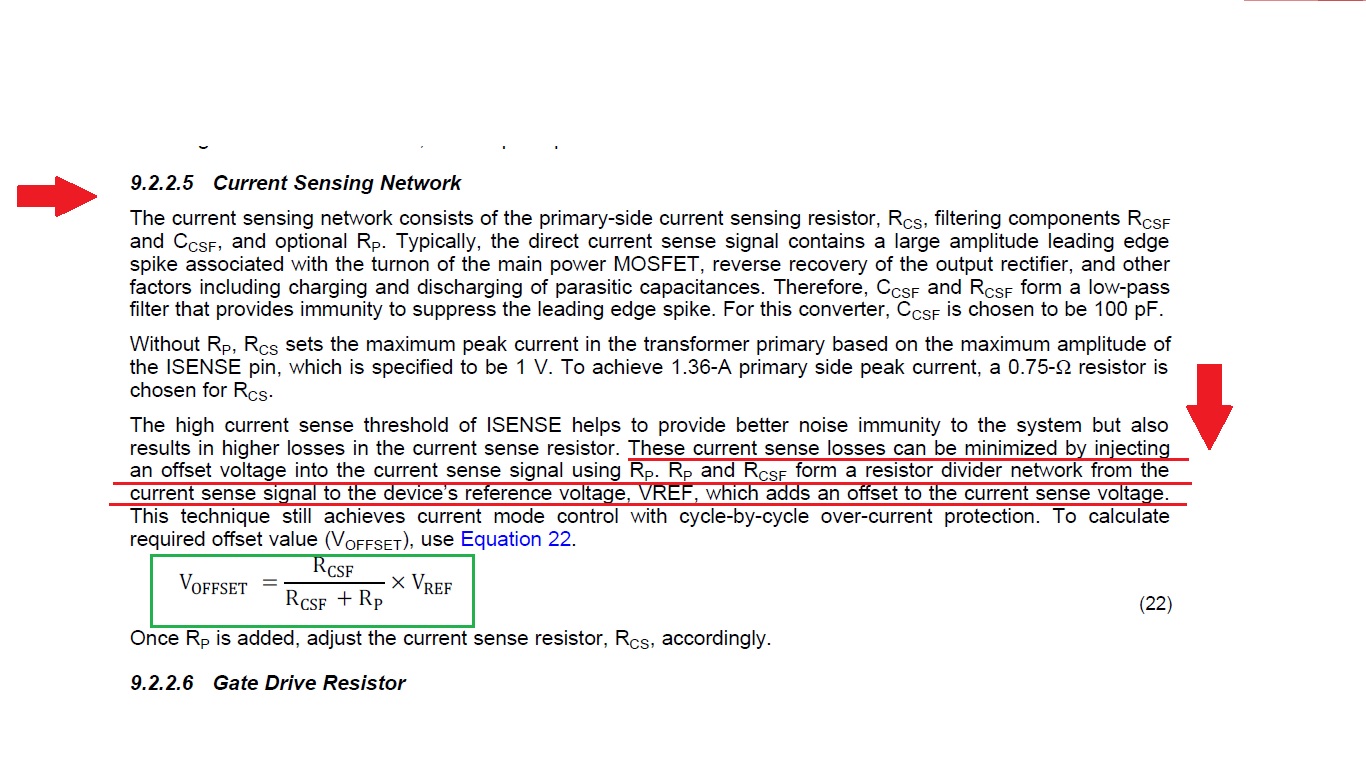
As per page number-25 Current sensing network design Equation number : 22.

Generally we can calculate Rcs value from maximum peak primary current, as we know when drop across Rcs higher than 1V it terminate the gate output voltage.

But according to datasheet we can reduce current sens losses by injecting extra voltage to Isens pin using Vref and voltage divider network.

I cant understand how it work? How 

VOFFSET = (RCSF × VREF) / (RCSF + RP) use and then how find Rcs value from it?

Sometimes in many design I have seen that one transistor connected with Vref pin and base pin connected with Ct (RT-CT network) . Really it is difficult to understand.

Can you please provide simplification ? with detail example and explanation  ?

Attached one file : in this case Ipk = 414 mA . (This simmulator design from TI web
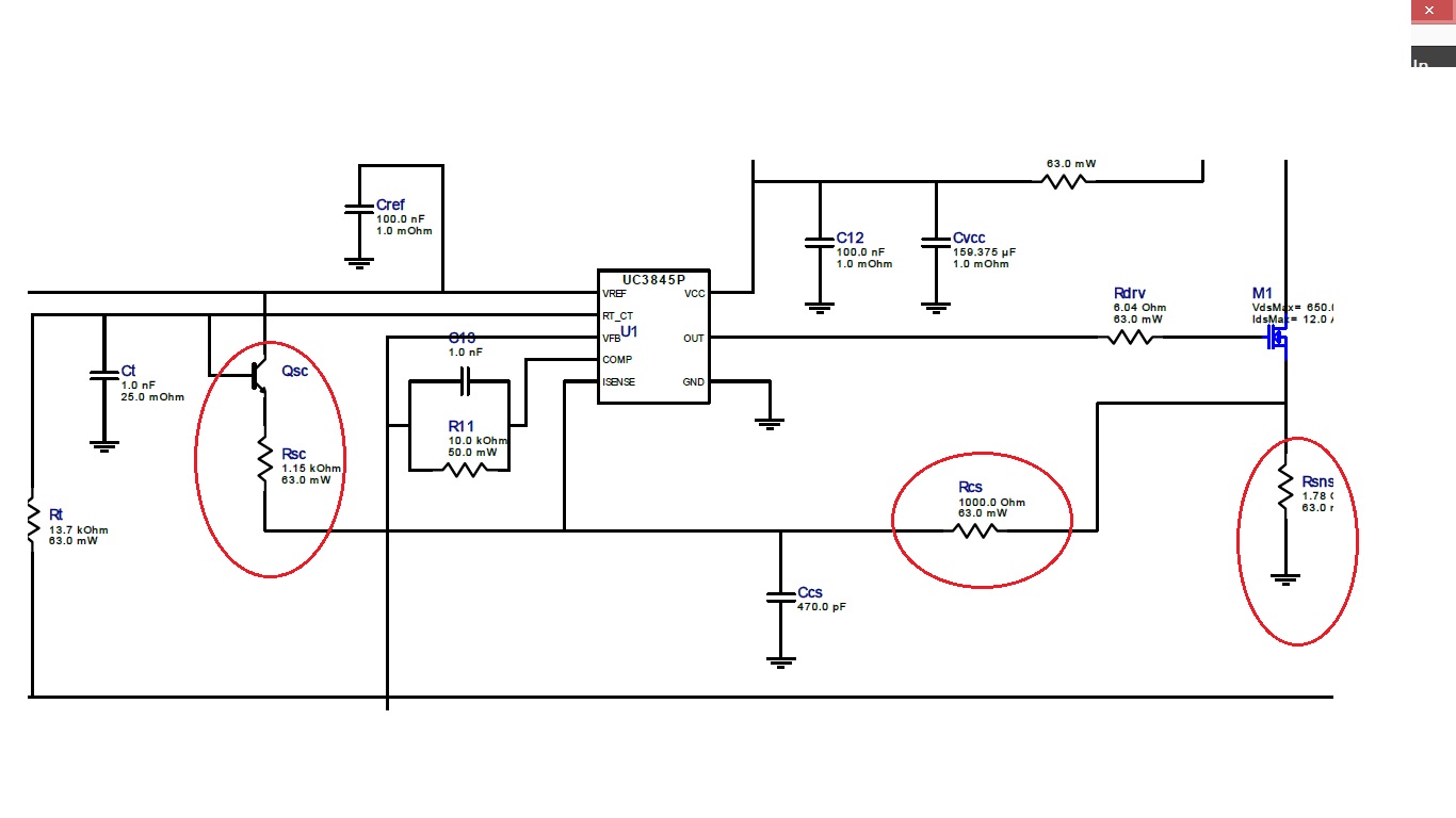
- bench online)

Looking for your support

Thanks :

Jaydeep Shah

radhey04ec@gmail.com

  • Hello Jaydeep,

    Where in the data sheet did you see 
    "according to datasheet we can reduce current sens losses by injecting extra voltage to Isens pin using Vref and voltage divider network."

    Regards

    John

  • Dear John ;

    Thanks for your reply , I attached screenshot of the Datasheet , Please check.

    1) I know ; It is for slope compensation to reduce peak -to average current error. But my question is : In my case maximum duty cycle is approx 12% , When maximum duty cycle is less than 50% then why require slope compensation in current mode pwm SMPS ? Generally it is useful for when Dmax is higher than 50% (because of system become un-satble at that time) . Can you please provide calculation steps for it ? I have checked many article like Lloyd Dixon TI Application note for slope compensation but calculation value does not matched with your schematic. (I have used TI online web-Design tool to generate schematic  and report).

    Here is attachment :

    My Design specification :

    Input AC voltage range : 180V to 350VAC

    IC - UC3845

    TYPE : ISOLATED FLYBACK

    Output voltage requirement : 5 V DC

    Maximum current requirement : 1- Amp

    2) Please also provide answer for following question , I cant find proper technical answer on internet.

     A) Why every manufacturer called "Offline converter" , what is the meaning of off-line term ? who coined it ?  

     B) As per generated report , when load current requirement is low (below 500 mA )  converter operate in DCM mode , when load current requirement is over 600mA Converter operate in CCM mode . Is it        possible converter operate in CCM and DCM as per situation ? if yes than how I can calculate parameters ? using CCM equation or DCM equation or boundary mode condition ?

    C) If converter operate in either CCM or DCM as per load current requirement than is it possible that converter provide constant voltage in any case ? I mean when load current requirement is 10 mA or 1 Amp (within range ) ?

    3) Will TI provide support to check my calculated value as per design requirement and provide suggestion/documents/link for better designing ?

    Dear , sorry for asking many question in single thread . But looking for your support.

    Thanks

    Jaydeep shah

    Email :radhey04ec@gmail.com

  • Hello Jaydeep,

    Its been a while since I read this section of the data sheet but I see now what you refer to.

    The application details a method of adding a DC offset to the current sense signal.

    Add a resistor divider with Rp and Rcs to the CS pin from the REF pin.

    For example you can set the offset at 0.75Vdc with the above equation and then calculate Rcs based on a 0.25V max sensed signal on Rcs

    This allows you to set the Rcs at a lower value and enjoy the benefits of higher efficiency.

    Im not sure how effective this method is in practice since I have not seen it used in any designs but it is worth considering.

    The rest of your questions refer to some particular circuit design that you have not attached.

    I recommend that you close this post and open a new post with all of the design information you feel is required.

    I can tell you that an offline converter refers to a power supply that has an high voltage AC input.

    Offline refers to the fact that the power comes off the "line" .

    Regards

    John