This thread has been locked.

If you have a related question, please click the "Ask a related question" button in the top right corner. The newly created question will be automatically linked to this question.

LP2951: About shutdown pin

Part Number: LP2951
Hello,

I have a question about LP2951-50.
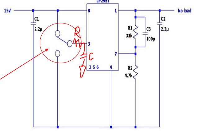
About shutdown pin
What happens if the shutdown pin is opened?
(Is it enabled or disabled?)
Is this state OK?

There is a period when the power is turned on = Hiz for the shutdown pin.

thank you.
  • Hi Ishii-san, 

    Shutdown pin is a logic pin to control the operation of the device. You have to drive this pin high or low, not open. If this pin is left open, the device could be in an unknown state. 

    In the datasheet, Figure 20, 21 show the startup behaviors when enabling the device using SHUTDOWN pin. 

    Regards, 
    Jason Song

  • Hello

    thank you for your answer.

    We are considering pulling up to prevent the shutdown pin from opening.
    What is the recommended pull-up resistor value? (About 100kΩ)

    Also shutdown pin in the attached circuit. When switching from H to L, the output rises to the input voltage.
    It may cause destruction of IC that leads to output.
    Does it happen because the switching starts quickly?

    Thank you.

    2768.LP2951-1.pdf

  • Hi Ishii-san,

    The 15V overshot was taken with a fixed 15V Vin while shutdown pin is switching low, is it correct? We would expect a little overshoot with enable transients, but 15V for a 10V rail is too much. Please see this plot fro datasheet.

    1. What's the minimum load in your system? I would suggest rerun this test with at least 1mA of load at the output.

    2. If you really need to have the switch, and you will need to have a RC to slow down the enable signal applied on the shutdown pin.

    Regards,
    Jason Song

  • Hi Ishii-san,

    Since you have to use a signal to control the switch, why not consider using the signal directly on the shutdown pin? 

    Regards, 

    Jason Song

  • Hello,

    thank you for your answer.

    I have additional questions.

    See the attached document for details.

    Thank you.

    LP2951-5.pdf

  • Hi Ishii-san,

    The datasheet has specifications on SHUTDOWN pin currents on Page 6. You can use this current to estimate the input impedance of the SHUTDOWN pin. At 25C, shutdown pin takes a 30uA at 2.4V, so the equivalent input resistance is around 80KOhms. Over temp, the leakage current on SHUTDOWN pin could go up to 100uA which is roughly 24KOhms. As SHUTDOWN pin's high threshold is 2V or above, when picking the pull-up resistor, with the voltage divider and the pull-up voltage,   you need to make sure that Rshutdown / (Rshutdown + Rpullup) x 5V > 2V. Actually, this pull-up resistor is really optional and you can directly apply the 5V to disable the LDO. 

    For some of the devices, SHUTDOWN pin can be left floating and this is because, in the design, there is internal pull-up or pull-down resistor. Without those resistors, this pin needs to have a high or low signal to ensure the device is in a known state. 

    Regards, 
    Jason Song