This thread has been locked.

If you have a related question, please click the "Ask a related question" button in the top right corner. The newly created question will be automatically linked to this question.

TPS65131-Q1: Output voltage unstability

Part Number: TPS65131

I have a problem with TPS65131. It can not regulate under load.

Designed output voltage: +5V -5V

Symptoms:

1) Input voltage: 3.3V    No load    

-5v output: fluctuating between -2v and -12v (If I add large electrolytic cap to C28, -5v stable with no load, but with 50mA load it goes down to 0v)

+5v output: 5v stable

------------------------------------------------------------------------------------------

2) Input voltage: 3.3V    270mA load on both outputs

-5v output: 0v

+5v output: fluctuating between 3.6v and 3.85v

------------------------------------------------------------------------------------------

3) Input voltage: 5v    No load

-5v output: -5v stable

+5v output: +5v stable

------------------------------------------------------------------------------------------

4) Input voltage: 5v    270mA load on both outputs

-5v output: 0v

+5v output: 4.7v (sometimes it goes down to 3v)

------------------------------------------------------------------------------------------

Schematic: https://i.hizliresim.com/p5NYb0.png

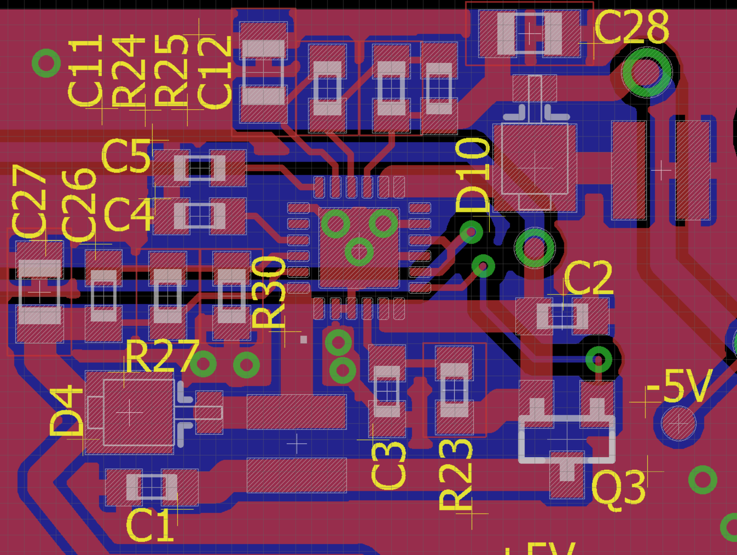
Board layout: https://i.hizliresim.com/kM8Y9W.png

Coil: vls3015cx-4r7m

Any help would be appreciated

  • Hi,

    I have notified our expert regarding this topic. Please expect a response by 9/6/19.

    Regards

    Shinya

  • Hello Mert,

    I am not able to see the schematics and layout by clicking the links you provided. It gives me an error 403 (forbidden). If you can embed your schematics/layout in the thread itself, I will review to see if I can spot something wrong with the design.

    Kind Regards,

    Liaqat

  • Hello,

    I reviewed the schematics and would suggest to insert a 51.1K resistor in series with the feed forward capacitors C26 and C12 on +5V and -5V side of net. We have seen that in some noisy designs, excessive noise coupling into feedback pins through these capacitors was causing instability and adding these series resistors improved it. Other than this, the rest of the schematics seems correct so I hope that this will solve the issue you are seeing.

    Kind Regards,

    Liaqat

  • I added 51.1K resistors, output voltages stabilized without load. But with 270mA load both outputs fail with audible noise from coil.

  • Can you please post VPOS, VNEG, and SW node wave forms for both converters shown on the same scope plot under loaded conditions? That may give some idea of what is going on.

    Kind Regards,

    Liaqat

  • Input: 4v  Load: 270mA

    +5v output  Yellow: VPOS  Blue: INP 

    Zoomed in:

    --------------------------------------------------------------------------------------------------------------------------------------------------------------------------------------------------------

    -5v output   Yellow: VNEG   Blue: OUTN

    Zoomed in: 

  • With PSP/PSN pins connected to GND and with 270mA load, the switching node waveform for inverting and boost converter should be continuous so I am puzzled as to why the waveform are discontinuous as switching seems to stop after some cycles. I don't see anything wrong in the schematics specially if you have added the 51.1K series resistors at C12 and C26. Could there be some board assembly issue? Is this just one board or do you have many boards behaving this way? Unfortunately, I don't have any other suggestions as to why the output should be unstable.

    Kind Regards,

    Liaqat


  • I assembled 3 different boards and all of them have the same problem.

  • Unfortunately, I do not have any other suggestions about why the VPOS/VNEG converters are not providing correct output under loaded condition. You may want to contact local TI sales office so that a field application engineer can take a look at your board and perhaps compare the signalling with a TPS65131 EVM in an effort to try and debug the issue.

    Kind Regards,

    Liaqat

  • I tried different things. While the PCB is hot +5v output is stable with 270mA load. So i tried masking the pcb and heating the components one by one. I found that heating R27 and R30 with hot air gun fixes my +5v issue. But i cant figure it out why this is happening. It cant be assembly issue, it is happening all of my 3 boards. I tried changing this resistors but no affect. 

    R30: Yageo RC0603FR-07180KL

    R27: Yageo RC0603FR-07562KL

  • Since these resistors  form feedback divider, it suggests some possible sensitivity to noise on FBP/FBN. Can you please try below two suggestions separately:

    -    reduce resistors R30 and R24 to 130K and recalculate R27 and R25 accordingly to achieve desired VPOS/VNEG voltage to see if this improves the behavior?The reason is: making more current flow through lower feedback resistor should reduce FB pin noise.

    -  make series resistors with C12 and C26, that I suggested earlier,to around 100K.

    Kind Regards,

    Liaqat

  • I changed R30 and R24 to 120K (i dont have 130K in stock) and calculated R27 and R25 accordingly, but this dont solve my issue.

    I changed series resistors with C12 and C26 to 100K and but no change. Same issue. 

  • Hello Mert,

    At this point, without actually having the board with me to test in the lab, it may be hard to figure out the cause of this issue. Unfortunately, I don't have any further suggestions.

    Kind Regards,

    Liaqat