This thread has been locked.

If you have a related question, please click the "Ask a related question" button in the top right corner. The newly created question will be automatically linked to this question.

TPS63030: TPS63030 extreme current draw from EN pin (>50ma)

Part Number: TPS63030
Other Parts Discussed in Thread: TPS62740

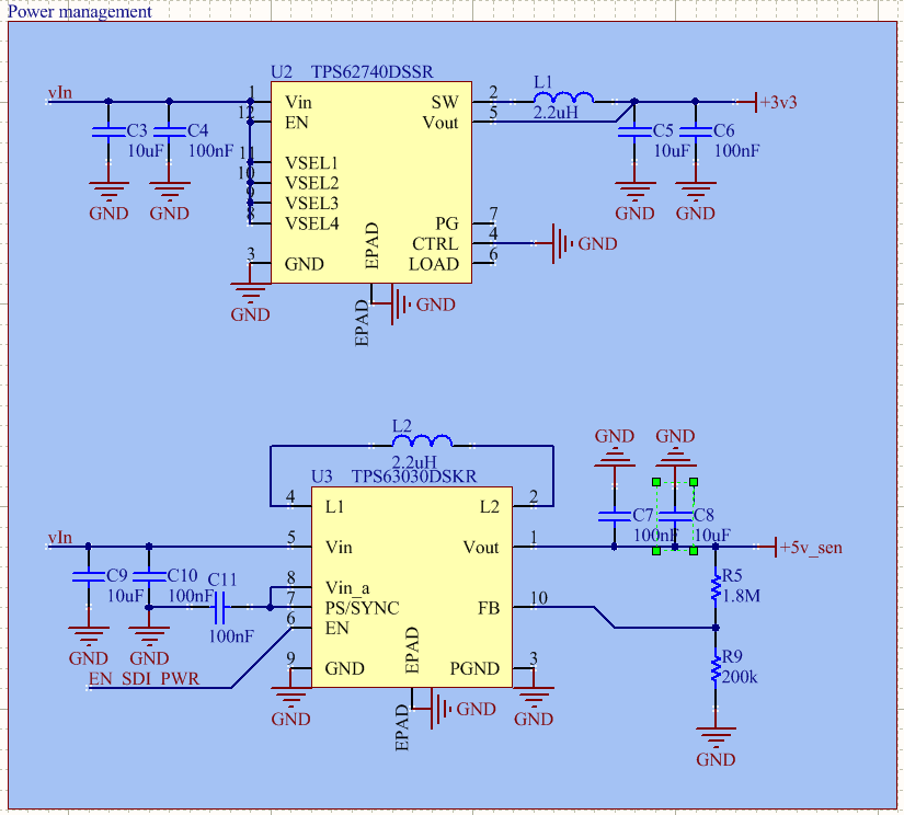
Hello, i have the following circuit

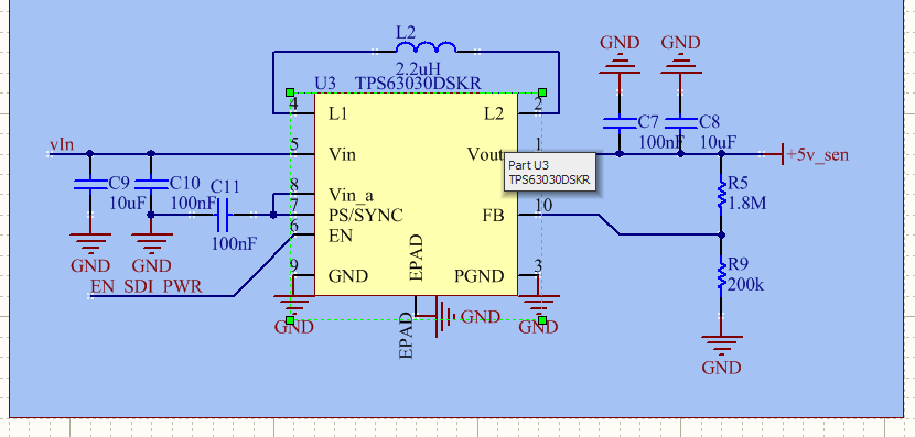
which is pretty much a copy of the one in the datasheet, with a small difference, the enable line is externally driven, in this case an atmega328p, interestingly when activating the en pin, not only the signal didn't activate

the voltage on the line was 0.8v, when shorting it to a 3v3 rail it started working, so i took a multimeter and measured the current going into EN pin, turned out to be around 50ma!

moreover, this is not an isolated case, i have repeated the measurements on 4 devices, and in all of them the same happens

normally i'd think this means a perforated fet, however i can be sure the voltage never went above 4.5v on any pin, hence being well within specification

the truth is that im quite out of ideas, this is an excedengly simple circuit yet it's giving a pretty surprising problem

any help is appreciated

  • Hi Diego:

    Thanks for asking.

    I did a test on TPS63030 EVM, and everything worked well. I didn't find the issue as you mentioned. (Vin from 0V-3V-0V, No load. Ven=3V, the Ien less is some uA.)

    May you share more details things to let me know about your system? What's the Vin range, and is there any other power supply in your system? During your test, is there any load?

  • Hi Minqui,

    There is indeed an other power supply, a TPS62740 one, this one behaves perfectly, with the whole circuit drawing less than 10uA with the uC in sleep

    Vin ranges from 3v to 5v in the most extreme cases, which were the ones tested the capacitors are all 25v rated (although i think its quite irrelevant for this particular situation)

    The EN_SDI_PWR signal is 3v3 (output from an atmega328p witha 3v3 supply [TPS62740]), it can be in high impedance state or high impedance with pull up aside from output

    Here is also the layout, R4 doesn't play in this circuit, is just a pull up for the reset of the uC, maybe there is some subtelty in the layout that im not seeing but honestly, id be surprised if it was the case, on the bottom left you can see the enable signal

    *edit, the maximum current drained is 80mA, however the same behavior appears when the output is open circuit

  • Hi Diego:

    Do you mind if we check the performance of TPS63030 firstly?

    Is there any new PCB in you hand? Please:

    1. Just solder new TPS63030 and the necessary surrounding components.

    2. Measure the impedance of the Vin, Vout, EN to GND.

    3.Use another power supply to control the EN pin with current measurement. 

    4.Configure the main power supply and reproduce the issue.

    If it appears, please measure the value of Vin, EN, Vout, VinA. Better with the waveform of L1, L2. Thank you!

  • hi again

    regarding 1: i did it, and it turns out that it worked, then when i soldered a moteino on top it stopped working, having the normal symptoms

    (moteino = reduced arduino with atmega328p)

    regarding 2:

    r vin apx 300k with other circuits soldered

    r vout >2M only capacitors on the net

    en >1G

    these measurements were made with a 34465A meter, the first 2 values are approximate since i didn't wait for the capacitors to fully charge

    and en was beyond the range of the multimeter

    3/4: i did so, when the moteino wasn't soldered it worked, as soon as the moteino was soldered and the signal activated, usual stuff

    the voltages are the following

    En: 0.8

    Vin: 4.79

    Vout: 0.1v

    VinA: 4.79

    L didn't oscillate, i put the oscilloscope in single mode and wasn't triggered

    the fact that this happens after soldering a micro controller board that has essentially nothing and systematically getting a failure has me mesmerized, especially since the tps32740 works perfectly

  • Hi Diego:

    Thanks for your supplement. I highly doubt the the issue should be caused by the Enable signal. 

    I checked the Enable signal source. The high state is High-impedance with pull up resistance. How about the low state?

    For TPS63030, it needs a certain value that higher than 1.2V to enable or low than 0.4V to disable. Float or high impedance is not acceptable.   


  • Hi minqui, I think you are referring to the default mode of the arduino pins?

    I actually set the pin as output and then write 1 on it, and that's the voltage I get, due to the current drained

  • Hi Diego:

    Sorry that I haven't used arduous before, just according to your mentions: "The EN_SDI_PWR signal is 3v3 (output from an atmega328p witha 3v3 supply [TPS62740]), it can be in high impedance state or high impedance with pull up aside from output" 

    May you cut off the line, and connect the enable pin to another power supply with 3.3V and measure the current? 

  • I actually did that, first message, about 50ma, looks like the input buffer was perforated or something but I can't possibly see why
  • Will test again just in case

  • Hello Diego,

    If 50mA are flowing into the EN pin, the IC is damaged as the leakage current on this pin is very low, see the electrical specification of the datasheet:

    A damage can happen if you apply a voltage outside the absolute maximum rating of the datasheet.

    Please check if you have a voltage shift between the GND connections of the Arduino and the TPS63030 EVM.

  • Brigitte im aware of that, what I don't know and is baffling me is that the chips are systematically breaking and the maximum voltage possible in the whole system is 4.8v, also there is an other supply which has the same max voltage ratings and works perfectly

  • Hello Diego,

    It is possible that you create overshoots above 4.8V and undershoots below GND in such a system when connecting cables to the board. These voltages can be a lot higher and lower than you would imagine if you never looked at them.

    You could minimize the issue for example with a series resistor on this pin. Then the ringing that happens during connecting the Arduino will be reduced.

    This pin is a high-impedance node and good design practice for high impedance nodes is to terminate it in general. But this is nothing specific to this pin, it is just good design practice to terminate all high-impedance input pins in a design.

  • Hello Diego,

    As I did not hear back from you, I expect the problem is solved and will close this thread. If you have further questions, add another post to reopen this thread or create another thread.

  • Hi Brigitte, sorry for the late answer, it was a trivia issue in the end, the board that drove this particular input had an other output pin connected to the driving pin, hence short circuiting to ground, making it appear as if it was the chip, sorry for wasting your time

    best

    Diego