This thread has been locked.

If you have a related question, please click the "Ask a related question" button in the top right corner. The newly created question will be automatically linked to this question.

LM5118: Buck-Boost Converter Dying

Part Number: LM5118

Hello,

I am building a supply that tops off a 940uF capacitor bank at an adjustable ~52.5V 

I was able to to get the circuit working but after unplugging/plugging in the 40v input the LM5118 would shut down and stop regulating. The EN pin is tied directly to the Vin.

I am waiting on more LM5118 to do more testing since I burned the first 5.  

Any idea what may be wrong based on the circuit?

Best,

-Danny

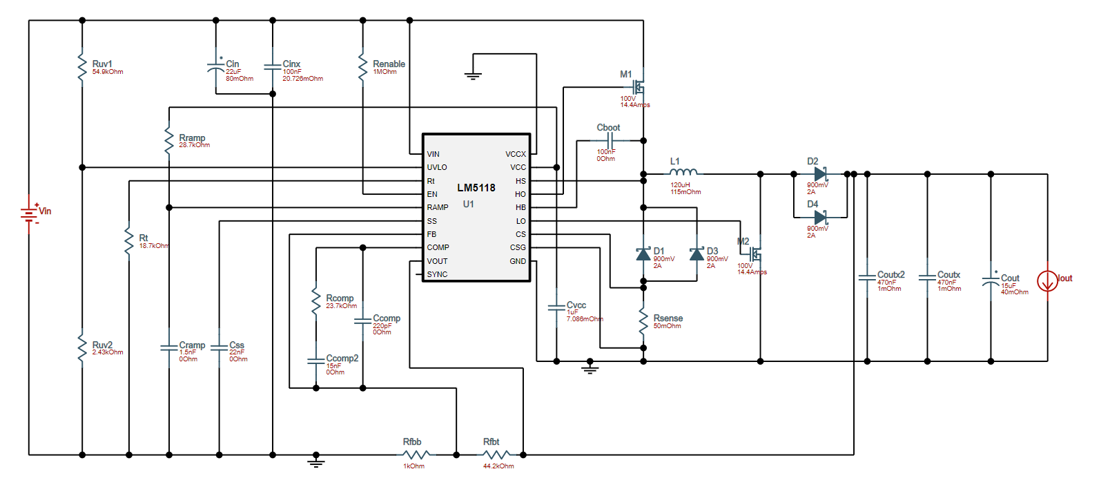
This the is WEBench circuit that I based my design on:

This the circuit that I have designed and implemented on PCB.

This is the PCB Layout:

  • Hello Danny,

    Thanks for reaching out with your question and for using the LM5118.

    Is the LM5118 being damaged or is the device just not switching? Can you please probe the VCC, UVLO and EN pins and let me know the voltage?

    Thanks,

    Garrett

  • Garrett.

    Got your measurements along with a few more.

    I did a today measuring the Vout, EN, UVLO,VCC, and FB pins.

    Vin: 48V

    1MOhm from EN pin to Vin.

    220k, 10k fb resistors which should give an output of 28.3v based on a vref of 1.23

    Picture1:

    Steady State

    Load: (47k + led)||(940uF)

    Yellow: En, Blue: Vout, Magenta: UVLO, Darkblue: VCC

    Note: good so far

    Picture2:

    On Startup

    Load: (47k + led)||(940uF)

    Yellow: En, Blue: Vout, Magenta: UVLO, Darkblue: VCC

    Note: good so far

    Picture3:

    On Startup

    Load: (1k)||(47k + led)||(940uF)

    Yellow: En, Blue: Vout, Magenta: UVLO, Darkblue: VCC

    Note: there is substantially more noise now that I added the 1k resistor across the output

    Picture4:

    Steady State

    Load: (1k)||(47k + led)||(940uF)

    Yellow: En, Blue: Vout, Magenta: UVLO, Darkblue: VCC

    Note:The output here measure to 14V with a multi-meter, this made me suspect that there is something wrong with the FB loop. So I started measuring the FB pin instead of EN in the following measurements

    Picture5:

    Steady State

    Load: (1k)||(47k + led)||(940uF)

    Yellow: FB, Blue: Vout, Magenta: UVLO, Darkblue: VCC

    Note: The FB pin has some horrible noise, other lines are also pretty bad. Im wasnt sure if this was because I was measuring the ground plane too far or there is actual noise so I soldering a ground wire to the AGND pin and started measuring ground from there.

    Picture6:

    Steady State

    Load: (1k)||(47k + led)||(940uF)

    Yellow: FB, Blue: Vout, Magenta: UVLO, Darkblue: VCC

    Note: Moving GND did not work, this is the actual noise on the FB pin...

    Picture7:

    Steady State

    Load: (1k)||(47k + led)||(940uF)

    Yellow: FB, Blue: Vout, Magenta: UVLO, Darkblue: VCC

    Note: The chip died as soon as i cycled it this time (i cycles it 7 times total in this experiment). Vout is 0v, Vcc is 0v

    Picture8:

    This is a picture of my measuring setup

    P1:

    P2:

    P3:

    P4:

    P5:

    P6:

    P7:

    P8:

  • Hi Danny,

    I took a second look at  your schematic and it looks like the VCC pin is is missing the capacitor from VCC to GND. I see it in the layout, what is the value of this capacitor.

    Thanks for providing the waveforms, based on these it looks like there is an issue between unload and a loaded condition (when the 1kOhm resistor is add). Is this a two layer board? Typically a 4 layer board is used to help shield sensitive signals with a ground layer.

    In picture 2 it looks like the output voltage is already up before the EN pin is pulled high. What does the start-up look like when the output voltage is completely discharged?

    Also please try replacing the feedback resistors with the values that were calculated by WEBENCH. The LM5118 has a voltage error amplifier and changing the top feedback resistor will change the loop compensation.

    -Garrett

  • 1) VCC has a 1uF cap on it.

    2) This is a 2 layer board, thus it may be an issue with interference.

    3) Picture 3 is the same at picture 2 but with 0 voltage on the output capacitors. I am going to do another measurement with my new setup below.

    4) I have replaced the resistors with the calculated WeBench values and replaced the capacitors with the right values as well. The values are exactly the same as the picture below:

    Here is a measurement I just took on startup:

    The output load is (47k + led)||(940uF) 

    Yellow: Vout    Blue: En    Magenta: FB    Darkblue: LO 

    The Vout takes about 2 seconds to reach 52.5v

    Here is the same measurement except I attached the 1k resistor across the output. This time the output does not reach 52.5V only to 13.4v

  • Something is very wrong with the FB. The FB voltage does not reach 1.23v when I have the 1k load across the output.

    With the smaller load the output voltage reached 52.5v and the fb pin is sitting at 1.23V as it should be.

  • At 37Vin and a 500Ohm load the FB pin drops to 220mV and the output drops to 9.3v compared to 13.4v at a 1kOhm load. 

  • Hi Danny,

    Check the UVLO pin. If the UVLO pin is getting pulled low then the LM5118 is entering hiccup mode.

    Based on the amount of noise on the FB pin I think it would be good to implement a 4 layer board to help minimize the noise.

    Garrett

  • Got it,

    I'll re-run the board with 4 layers and get back to you.

    UVLO seems to be fine

  • Danny,

    Sounds good. If you have any other questions please create a new post. I am closing this issue.

    Thanks,

    Garrett

  • SOLVED! 

    I ran a 4 layer pcb and got the system to work with a 360Ohm load @ 52.5Vout and 36-60Vin

    WOOOHOOO super happy with this working! thanks for all the advice!