This thread has been locked.

If you have a related question, please click the "Ask a related question" button in the top right corner. The newly created question will be automatically linked to this question.

TPS544C25: Non-Monotonic Startup

Part Number: TPS544C25

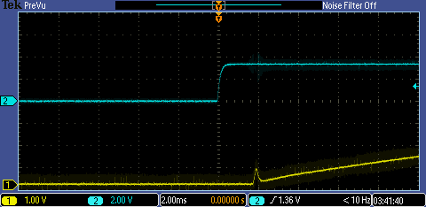
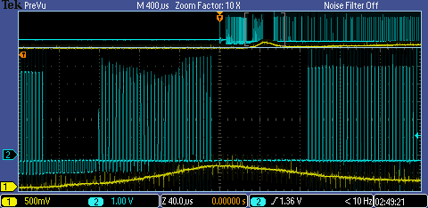
I am using the TPS544C25 to regulate a 3.3V output.  The chip works fine and can regulate and load step, the only issue is that during startup, there is a small peak as the voltage rises from 0V to 3.3V.  Whether it starts from no load or full load the issue still persists.  I have attached a picture for reference.  The yellow/orange line is the output voltage and the blue line is the voltage on the comp pin of the chip.  I do not understand why the comp pin is going to 0 when the peaking occurs.  I looked at the datasheet and the peaking seems to occur when the reference voltage hits the bottom of the ramp signal.

The converter operates from 12V to 3.3V.

If I start the converter up with some output voltage still on the capacitors, the startup rise is monotonic and everything works well.

Any help is appreciated thanks.

  • Hi Christopher,

    I have several questions that will help us understand the issue better:

    Can you please share a schematic snippet, and if not possible, the inductor value, output cap values, switching frequency setting?

    What is your load - is it a resistor, electronic load in constant current, etc? If an electronic load, what model? Is the electronic load OFF when you say no load? What is the full load current?

    Are you enabling the device with CNTL or just allowing VIN startup?

    Can you please also share oscilloscope waveform with the 12V input, VOUT, SW, COMP?

  • I cannot provide a schematic snippet, but I can provide some values.

    The input capacitance is 220 uF, Output capacitance is ~950uF, the inductor value is 10 uH, and the switching frequency is 290 kHz.

    The load I showed in the previous picture was at no load, not connected to anything at all.  However, when I power up the load with a constant resistance or constant current, the issue still persists.  The full load current is 6A.

    The controller is fed by an enable signal, which turns on first before the output voltage starts to rise, I will include a picture.

    ENABLE SIGNAL (BLUE), OUTPUT VOLTAGE (YELLOW):

    VIN (BLUE), VOUT (YELLOW):

    SW (BLUE), VOUT (YELLOW), sorry for bad quality, I could not get a good picture:

    So, this power converter is initially fed by a 5V bus, which will turn to 12V when all of the supplies are up and running after some time, much later than the startup time.  I am only seeing the issue from the 5V bus, I will try the 12V input tomorrow (there are some changes on the board that I need to make).  The enable is on well before the input voltage starts to rise, but I am seeing a small dip on the input voltage.  It is not nearly enough to trigger UVLO (3.7V from the datasheet), so I do not think it is that big of a deal.  The switch node does start to pulse, however, when the "blip" occurs it pulls low for 100 us and then resumes normal operation and rises smoothly to the output voltage.

    The only thing that I can see that may be troubling is the 5V input voltage.  I will try with a 12V bus and update.

    Thanks

  • UPDATE:  I found my problem.  I am using a parallel protection FET for this power supply, but I was sensing after the FET, not before.  So the output was rising, but the FET was not on yet, so when the FET finally turned on, the feedback and compensation were at different points and the controller was expecting a different value.  It looks like a transient to the controller, so it was shutting off controller until the comp pin and feed back matched.  This issue is solved.  Thanks