This thread has been locked.

If you have a related question, please click the "Ask a related question" button in the top right corner. The newly created question will be automatically linked to this question.

TPS65218: LDO - Output observed at 2.2V and Oscillating. DC-DC output only 500mV

Part Number: TPS65218
Other Parts Discussed in Thread: AM4372,

I'm using TPS65218D0 to power AM4372 processor. During testing, it was observed that output from DC-DC converters 1, 2, 3 & 4 were only 500mV.

Design and component values are similar to the application note. Output values are 1.1V, 1.1V, 1.35V, 3.3V for DC-DC converter 1, 2, 3 & 4 respectively.

AC_DET is connected to 5V, PFI is set at 4.5V, PWR_EN is pulled up to 1.8V supply and also connected to RTC section of processor, Push button input is pulled up to 5V and

momentarily connected to GND using a push button.

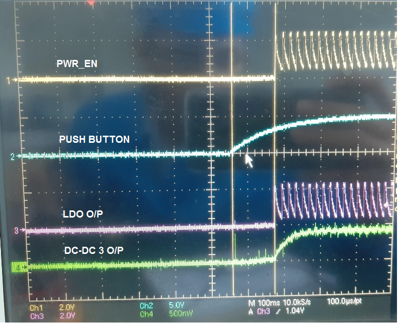
It was observed that LDO output was at 2.2V for ~4mS and then starts decaying. LDO output is shown in CH.1 and PFI input is shown in CH. 2.

(As mentioned earlier, I am using the default values - so I was expecting 1.8V with 2% tolerance.)

LDO output and DC-DC converter 3 output:

Output load on the DC-DC converters were removed and the same above mentioned behavior was observed. But, LDO was connected to AM4372 RTC section, as we didn't have 0ohm in the LDO line.

nWAKEUp and PFO signals were trying to come-up but since LDO was going LOW, since they were pulled to 1.8V supply. 

The above mentioned observation was repeatable and was observed in 3 boards.

Please can anyone share if they have observed similar issue and the required fix.

Your help will be much appreciated !

Thanks,

Aravind

  • Aravind,

    This is not an oscillation, which would happen at a much higher frequency. What you are seeing is a power-up sequence, followed very quickly by a power-down sequence. It does not make sense that the DCDCs are all 500mV and they never fully go down to 0V, but it is still clear to me from the LDO1 waveform and the timescale (10ms/div, 20ms/div) that the PMIC is trying to power-up, detecting the incorrect voltage for every rail, and then powering down.

    Please share the schematic for TPS65218D0 or there is nothing further I can do to debug this issue.

  • Thanks Brian,

    I agree, it is not an oscillation. 

    I have requested Brad Caldwell to share the schematics with you.

    Please note that we have already reviewed the schematics with TI team and no issues were reported.

    Thanks,

    Aravind

  • Brian,

    I removed PMIC from board and fed the DC supply rails (1.1V, 1.1V, 1.35V, 3.3V, 1.8V) externally using bench top DC power supplies. No overload was observed in any of the power rails and the processor started functioning.

    Hope this helps.

    Thanks,

    Aravind

  • Aravind,

    During first power-up sequence, please measure 4 channels on oscilloscope:

    • PWR_EN
    • PB
    • LDO1
    • DCDC4

    It appears to me that LDO1 is causing the problem. You see that VLDO1 = 2.2V, but it should be 1.8V and the STRICT bit is set to 1b by default.

    When STRICT=1b, VOV = 105% Max = 1.05*1.89V, so it makes sense that the PMIC shuts down because VLDO1 is too high (over-voltage).

    The question is: why is LDO1 too high? What happens when you remove the connection from +1V8 to +1V8_RTC (R67) and measure at the +1V8 net (TP115)? In your original thread, you said:

    Aravind Sridharan said:
    Output load on the DC-DC converters were removed and the same above mentioned behavior was observed. But, LDO was connected to AM4372 RTC section, as we didn't have 0ohm in the LDO line.

    But this does not make sense to me. If 0-Ohm is removed, LDO is not connected to +1V8_RTC anymore.

    It is very hard to say if LDO1 > 1.8V before or after DCDC4 = 3.3V, as you did not provide a scope shot for this yet. But it is my assumption that, without any other external DC-DCs or LDOs on the board, that LDO1 must be 1.8V exactly for 1-2ms before DCDC4 turns on. Somehow, when DCDC4 turns on, it is creating a leakage path through AM437x from 3.3V to 1.8V due to the fact that DCDC5 and DCDC6 are not used. It would be easier to determine after looking more closely at the scope shot I requested.

  • Thanks Brian,

    I will get you those 4 traces soon. After that, I will also try removing the DC-DC channel 4 inductor, to see if there is any change to LDO output.

    Regarding 1V8_RTC: I tried both the options, keeping R67 populated and R67 as DNP. In both the cases, the same LDO behavior was observed.

    Though I can isolated 1V8_RTC section from 1V8 by removing R67, other Processor power pins were getting 1V8 supply.

    Warm Regards,

    Aravind

  • Aravind,

    It makes more sense to keep R67 populated because this is the supply for RTC rail #1. The only way to test LDO1 with no load would be to cut the trace and I don't know if that is possible on your PCB.

    This brings up another point I noticed on the schematic: CAP_VDD_RTC does not receive power from anywhere. The schematic shows R314 is DNI, which is the connection from CAP_VDD_RTC on AM437x chip to +1V1_CORE rail.

    I do not know the impact of this from the AM437x, but it is a surprise to me that this rail has no power, because it is RTC rail #2 (the second rail to turn on when DCDC5/6 are used).


    Still looking forward to seeing those scope shots you capture. Thanks!

  • Aravind,

    It would be interesting to see if your board performs correctly with DCDC5/6 passive circuitry fully populated, since this is just an assembly change and the component pads are already on the PCB.

  • Brian,

    Please find the scope traces.

    1. When Power Enable is pulled to 1.8V_RTC. Please note that the channels have different voltage scales.

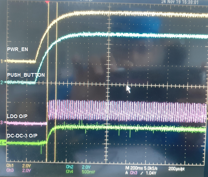
    2. When Power Enable is pulled up to 5V input. Please note that the channels have different voltage scales.

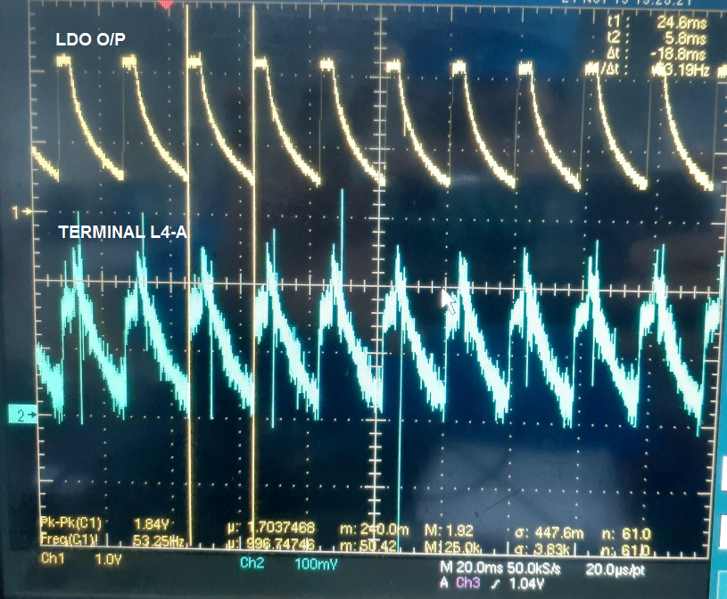
    3. After removing inductor and probing in L4-A pin. So, this shows that PCB layout is not impacting LDO behavior.

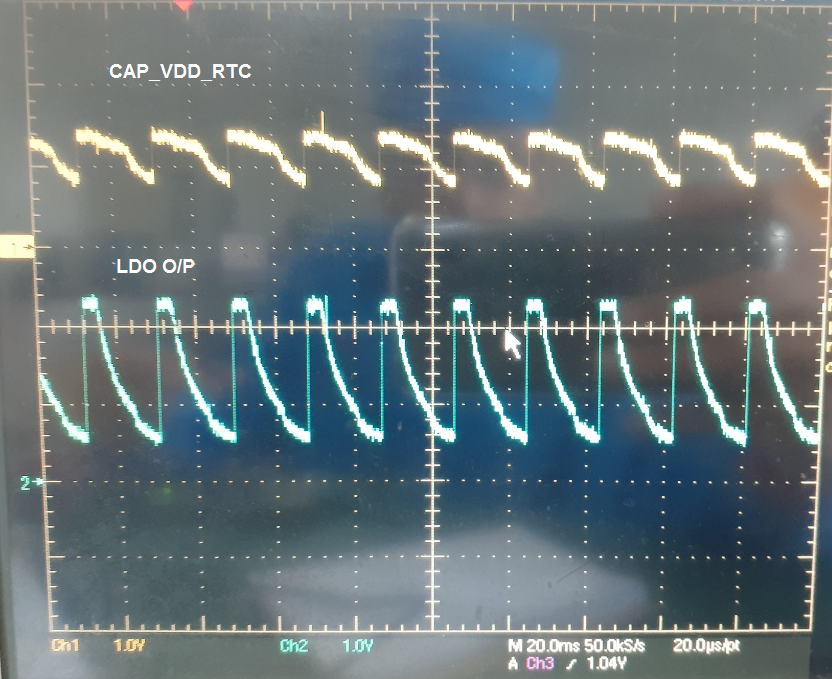
    4 (A) Reg: CAP_VDD_RTC Power: I have connected RTC_KALDO_EN to GND through R68. So, R314 was kept as DNI. Below is measurement from CAP_VDD_RTC pin

    4(B). When the CAP_VDD_RTC is powered from +1V1_CORE (by populating R314 and disabling RTC_KALDO_EN).

    Same LDO behavior was observed.

    5. With IN_BU and CC connected to GND, terminals L5-FB5 connected to GND, terminals L6-FB6 connected to GND,

    Same LDO behavior was observed.

    6. When I populated inductor for L5 terminal, I observed 1V output in the DC-DC 5. Similarly observed, square wave pulses in L6 terminal too, so hopeful that  DC-DC 6 will work.

    But same issues were observed in LDO, DC-DC 1, 2 & 3.

    7. 3V was observed in INT_LDO pin.

    Regards,

    Aravind

  • Aravind,

    Most of these scope shots say "DC-DC-3 O/P", and one of them says "Terminal L4-A". 


    When don't any of them say ""DC-DC-4 O/P", as in the output pin of DCDC4?

    Maybe ""DC-DC-3 O/P" is a typo and it should say 4 instead of 3. I cannot tell where you measured so I would like to confirm.

  • Brian,

    Sorry, it was a typo error. I should have mentioned it as DC-DC-4 O/P

    DC-DC-3 O/P in above pictures are 3.3V output rail, measured at Pin 15. 

    Terminal L4-A measurement, is after removing the inductor of 3.3V converter and measuring at L4-A, Pin 13.

    Regards,
    Aravind

  • Aravind,

    The root cause of this issue is as follows:

    The Thermal Pad of the TPS65218D0PHP IC is the main GND connection. There are not any dedicated GND pins on the perimeter of the device (pins 1-48).

    In your design, it appears that there are vias underneath the Thermal Pad but there is no exposed copper (and the stencil will not have any holes for solder to land on the vias).

    The result is that there is no electrical connection from the Thermal Pad to the board GND. 

    This is what causes LDO1 to overshoot (which is because INT_LDO shifts up from 2.5V to ~2.8V when LDO1 begins to turn on in the power sequence).

  • Brian,

    As TI team pointed out, the GND pad of IC was not getting connected to board's GND. After rework, the PMIC output was working good as expected.

    Thank you very much for your help !

    Regards,

    Aravind