This thread has been locked.

If you have a related question, please click the "Ask a related question" button in the top right corner. The newly created question will be automatically linked to this question.

LM5066: LM5066 shut down the FANs with bit 3 and 9 set (HFCB)

Part Number: LM5066

I am testing a FAN controller board in a thermal chamber and have encountered a weird failure. FAN controller has 4 fans, 3A, 54V each. Each fan connected to an LM5066. FAN speed could go up to 16500 RPM.

At 0C, when I ramp up from 4000RPM to 16500RPM, sometimes FAN1 and FAN2 shut down by LM5066. Note that the failure is not during start-up, but when FANs are running at lower speed (4000RPM) and ramped up to 16500RPM.

LM5066 register E1 is 0AC8 for the two failed FANs and is 0888 for the functional FANs.

Comparing the registers, notice that:

Bit 3 (IIN_OC) is set in all 4 LM5066 devices

Bit 6 (DEVICE_OFF) is set in 2 failed LM5066 devices (makes sense)

Bit 9 (TIMER_LATCHED_OFF) is set in 2 failed LM5066 devices.

 I am not sure why Fault timer is expired, doesn’t it only run during the start-up?

I have also exchanged failed fans 1,2 and 3,4 and the failure followed the LM5066 location not the FANs.

  • Hi Flavio,

    The load step can generate di/dt which develops large differential voltage across the current sense lines due to parasitic inductance as shown below and Fig-11 in http://www.ti.com/lit/an/slva703/slva703.pdf . Please populate the filter cap and check.

    BR, Rakesh

  • Hi Rakesh,

     What should be the value for the Cfilter?

    Should we increase the Fault timer as well?

  • Hi Flavio,

    This has to be iterative as it depends on the duration & peak of your load transient. You can start with Cfilter to get time constant of 200 ns and increase ..

    Yes, you can also adjust fault timer provided your design does not fail in meeting SOA margin.

    BR, Rakesh

  • Hi Rakesh,

    Can you give me  cap value for Cfilter based on my schematic (e-mailed)? By 200nS time constant you mean i need to add Rfilter as well?

    In HFCB design I have huge SOA margin, isn't it better to increase fault timer  Ct only?

  • Hi Flavio,

    It is better to avoid circuit breaker fault to trigger. So, start with Rfilter=1 Ohm, Cfilter = 220nF and increase Cfilter if needed till 470nF.

    BR, Rakesh

  • Hi Rakesh,

    a bit update.

    1. I tried Cfilter 220nf only, I did not have a 1-OHM resistor, so Rfilter=0ohm. it did not help, hotswap shut down a fan.
    2. I then tried increasing the fault timer from 0.5mS to 5mS (10nF to 100nF), still hot swap shut down. this issue only happes at 0C when I ramp up fans from 4000 to max RPM 17000. at room and 40c it works so far.
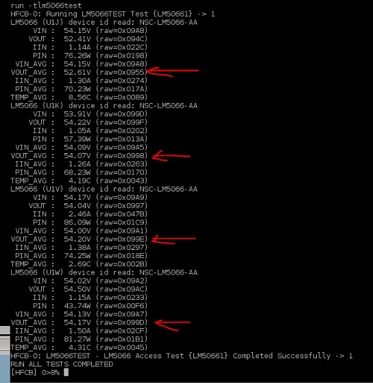
    3. Not sure why I see lower Vout at channels 3 and 4 when read LM5066 registers, (see below log).
    4. LM5066 E1h register for good fans were 0888 and for the failing fan was 0AC8.
    5. Register 7ch=04 (OC fault)

    I will probe the board tomorrow. any specific signals you need to see?

    ++++++++++++++++++++++

    checking voltage curent and power after failure:

    LM5066 (U1J) device id read: NSC-LM5066-AA
         VIN :  54.44V (raw=0x09B5)
        VOUT :   1.87V (raw=0x003E)    <==failed
         IIN :  -0.00A (raw=0x002C)
         PIN :  -0.22W (raw=0x001B)
     VIN_AVG :  54.24V (raw=0x09AC)
    VOUT_AVG :   1.83V (raw=0x003C)
     IIN_AVG :  -0.01A (raw=0x002A)
     PIN_AVG :  -0.62W (raw=0x0019)
    TEMP_AVG :   7.81C (raw=0x007D)
    LM5066 (U1K) device id read: NSC-LM5066-AA
         VIN :  53.96V (raw=0x099F)
        VOUT :  54.17V (raw=0x099D) <==looks fine
         IIN :   1.96A (raw=0x039D)
         PIN :  80.27W (raw=0x01AC)
     VIN_AVG :  54.11V (raw=0x09A6)
    VOUT_AVG :  54.24V (raw=0x09A0)
     IIN_AVG :   1.27A (raw=0x0268)
     PIN_AVG :  68.83W (raw=0x0173)
    TEMP_AVG :   7.31C (raw=0x0075)
    LM5066 (U1V) device id read: NSC-LM5066-AA
         VIN :  54.07V (raw=0x09A4)
        VOUT :  39.02V (raw=0x06E6)  <==why the voltage has dropped?
         IIN :   2.21A (raw=0x040D)
         PIN :  85.89W (raw=0x01C8)
     VIN_AVG :  54.17V (raw=0x09A9)
    VOUT_AVG :  37.85V (raw=0x06B0)
     IIN_AVG :   1.92A (raw=0x0389)
     PIN_AVG : 103.96W (raw=0x0222)
    TEMP_AVG :  30.88C (raw=0x01EE)
    LM5066 (U1W) device id read: NSC-LM5066-AA
         VIN :  54.20V (raw=0x09AA)
        VOUT :  37.45V (raw=0x069E) <==voltage dropped?
         IIN :   1.94A (raw=0x0392)
         PIN : 135.47W (raw=0x02BF)
     VIN_AVG :  54.31V (raw=0x09AF)
    VOUT_AVG :  37.28V (raw=0x0696)
     IIN_AVG :   1.93A (raw=0x038E)
     PIN_AVG : 104.76W (raw=0x0226)
    TEMP_AVG :  59.19C (raw=0x03B3)
    HFCB-0: LM5066TEST - LM5066 Access Test {LM50661} Completed Successfully -> 1
    RUN ALL TESTS COMPLETED
    [HFCB] 0>20%

  • Hi Flavio,

    If you can probe few test waveforms , it would be very helpful for me.

    Capture below nodes for each LM5066 portion.

    • Vin, Vout, Timer voltage, GATE voltage
    • Vout, Timer voltage, GATE voltage, input current 

    BR, Rakesh

  •  Hi Rakesh,

    I ran a few experiments today to find out if the issue is with the board or the FAN as follows:

    1. Set the board in the chamber. Chamber set to 0c, set 4 fans to max RPM. FAN 1 failed first. After a few seconds FAN 2 failed. FANs 3 and 4 did not fail. (duplicating original issue reported).
    2. I used an extension wire and set FAN1 outside the thermal chamber so it’s not exposed to the cold temp. Set the chamber to 0c, RPM to max. FAN1 failed outside the thermal chamber. So the issue is with the board, not the FAN.
    3. I set a second board inside the chamber. This was to make sure the 1st board is not defective. Set chamber to 0c, RPM at max, FAN1 failed. Same as the first HFCB. So it’s not board dependent.
    4. Currently HFCB hotswap CL (Current Limit) is set to 26A. I reworked the board and increased CL=50A. it did not help. FAN 1 failed at 0c and max RPM.
    5. Also ran the following experiments:
        1. Set FAN1 only outside the chamber. It worked fine at 0c and max RPM.
        2. Added FAN2 . Both fans worked fine. No shut down.
        3. Added the third fan, FAN1 failed.

    So somehow more than 2 FANs at high speed and 0c causes FAN1 hotswap to shut dowan.

    Can you please review the schematic, I have 4 of B380-13-F at the output of each hotswap, could that cause issues?

    I plan to probe the board tomorrow.


  • Hi Flavio,

    Failed - you mean LM5066 shut down right and not physical damage to either LM5066 or FET  ?

    All these FANs are powered from the output of Single LM5066 device  or  each has it own LM5066 ?

    B380-13-F will not cause this cause.

    Can you share full schematic and layout ?

    BR, Rakesh

  • Hi Rakesh,

    yes by failed I mean LM5066 shut down power to the FAN.

    Each Fan has it's own LM5066.

  • Hi Rakesh,

    since it shut the FAN down at 0c (low temp), does LM5066 monitor and shut down for being under temperature? I see the over temp being monitored, but how about under temp?

  • Hi Flavio,

    LM5066 does not take any action for under temperature.

    Did you manage to get some waveforms ?

    BR, Rakesh

  • Hi Rakesh,

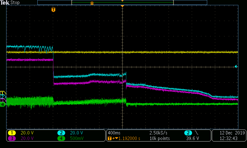
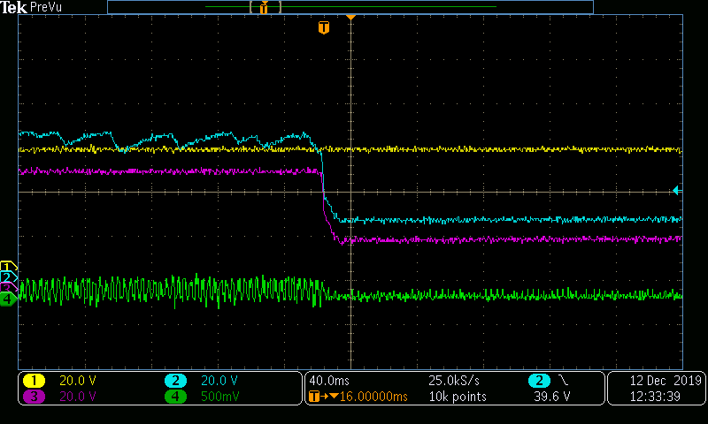
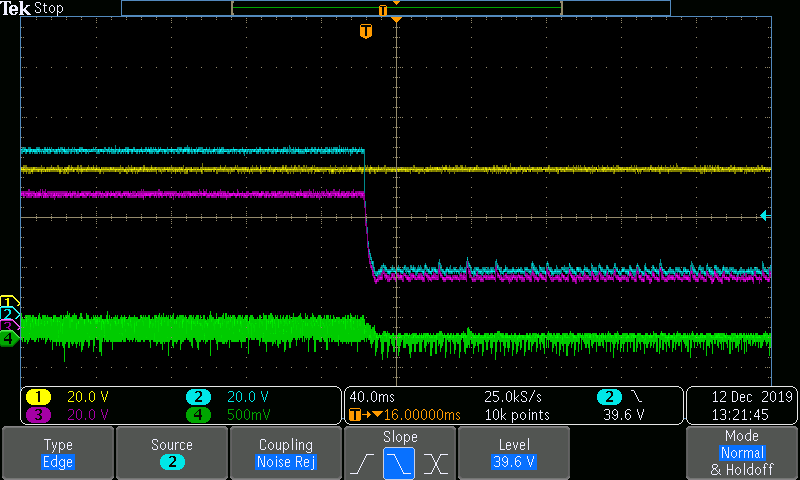
    the scope captures attached.

    Captures 1 and 2 at 0c and 16500RPM (MAX RPM), I see some oscillation at the gate before shut down the FAN.

    the third capture is the same FAN at 25C, 16500RPM, gate is stable. I manually shut down the FAN by writing 00 to register 01h, otherwise it won't shut down.

    AA

    h1=drain

    ch2=gate

    ch3=source ( FAN)

    ch4=current (100mv=1A)

  • Hi Flavio,

    The pulsed load from the FAN might be triggering the circuit breaker event and causing the GATE to drop but before shutdown the system is getting out of circuit breaker event. 

    Probing Timer pin voltage will give us more clarity. Can you check that ? Is it possible to probe the actual input current or source current of the MOSFET (just before the output cap) ?

    BR, Rakesh

  • Hi Rakesh,

    Why this only happen at low temperature? Recall that I increased the timer from 0.5ms to 5ms, but did not help.

    AA

  • Hi Flavio,

    Does the load profile changes with temperature (low impedance as temp drops)? Because, from device side, we would not expect change in CL threshold as shown in Figure 12. Current Limit Threshold vs TJ in the datasheet. 

    Increasing timer value may not help. As you see below, the GATE starts to drop when the timer starts clocking for a load step. 

    Subsequent pulse load steps would lead to GATE shutdown as illustrated below. To root cause, we need to probe in detail at the first instance. Unfortunately, it is difficult but there is no other way to debug. 

    BR, Rakesh

  • Hi Rakesh,

    I can probe the timer voltage Monday. To pinpoint if the issue is from the HFCB or the fan side, I used extension wire and installed the FAN outside the thermal chamber. So HFCB was inside the thermal chamber at 0c and the FAN was at 25C. In this case, hotswap still shut down the FAN proving that the issue is on the HFCB hotswap side not the fan. I will check with the FAN vendor if the load changes with themerature or fan speed.

    AA

  • Hi Flavio,

    Ok. Understood. Please capture the waveforms. we can discuss on call.

    BR, Rakesh

  • can you please also review the schematic. I have total of 4 Zener diodes (B380-13 F) at the output of the hotswap (source) before each FAN connector for the free wheeling. could that be an issue?

  • More Schottky diodes in parallel would not cause any issue.  In fact these help in a positive way to freewheel the inductive current during turn off.

    Please capture waveform along with timer for tomorrow's call.

    Best regards, Rakesh

  • Hi Flavio,

    Please close here as I am following up on email.

    BR, Rakesh

  • Hi Flavio,

    Please share your test results 

    BR, Rakesh

  • Hi Rakesh,

     I Added 100uf cap to the source  of the power FET before the FAN connector. originally we had 66uF, total is now 166uF, please refer to the schematic i e-mailed. It is passing at 0c with multiple power cycles. The Rsense is kept at 5mOHM. I do not see any change in the max current.

    Can you please explain how adding 100uf BEFORE THE fan helped?

    AA

     ?


  • Hi Flavio,

    More output capacitance is acting as buffer to support the pulsed load of the Fan.

    Regarding max current,  are you measuring with high bandwidth current probe.?

    Set your current limit at least 20% above your max load current to avoid false shut down issues.

    BR,  Rakesh

  • Hi Rakesh,

    Fan Max current is 3A. i set the LM5066 CL to 5.2A. it seems enough headroom but since I have 4 fans on the same power bus, could the imposed ripple current become significantly more complex as the currents of each fan add and subtract with each other eventually causing LM5066 to shut down?  If correct,  adding more caps at the fan side seem to reduce ripple current and let fan continue to run.

    AA

  • Hi Flavio,

    Yes, the large differential voltage between Vin to Vout due to pulsed/ripple current would trigger current limit or circuit breaker. The capacitors would help in that case.

    Best Regards, Rakesh

  • Hi Rakesh,

    I have 66uF cap at the output of the LM5066, just before the FAN connector for each fan.  I successfully tested by adding a 100uF (total cap 66uF+100uF) and then 47uF (total 66uF +47uF) and both worked, so I am guessing the 66uF output cap is marginal but not enough. Is there a way to calculate minimum capacitor required at the output of LM5066?

    AA

  • Hi Flavio,

    As far as I know, the general thumb rule is to use 1uF per 1W of load. For example, your FAN load draws a peak load current of 3A at 50V then 150uF for this 150W load is reasonably good enough. Take care to select low ESR type capacitors. Also use 1uF ceramic cap at the o/p of LM5066 for better filtering.

    BR, Rakesh

  • Hi Flavio,

    Please let us know if there are any further questions.

    BR, Rakesh

  • Hi Rakesh,

    I am testing with 200uF cap at each FAN input.

    can you clarify "Also use 1uF ceramic cap at the o/p of LM5066 for better filtering" comment? what do you mean by O/P? what is the pin number?

    AA

  • Hi Flavio,

    I meant to add 1uF at the output bus (source of the hot-swap MOSFET or OUT pin of the LM5066) to support the transient current for the load.

    BR, Rakesh

  • Hi Rakesh,

    I have 1uF and 0.1uF at the source.

    AA

  • Hi Flavio,

    Yes, I see. Thanks!

    BR, Rakesh

  • Hi Rakesh,

    Increasing C-load from 66uF to above 100uF seems to work. I added 200uF bulk cap before each fan connector. Hotswap does not shut down the Fan anymore at 0c and max speed.

    AA