This thread has been locked.

If you have a related question, please click the "Ask a related question" button in the top right corner. The newly created question will be automatically linked to this question.

UCC28180: UCC28180: TIDA-00652

Part Number: UCC28180
Other Parts Discussed in Thread: TIDA-00652, DRV10983,

Hi

I have been experimenting with the reference design TIDA-00652 , I have seen few issue over period of testing . I am facing two issues.

1. The SMPS does not go in protection mode even if the draw on the output is over 30watts, so over 24Vdc at 1.25 AMP, I have checked the values of the resistors and R2,R3 and R6 have 1% variation in the values. Similarly R16 and R17 are 191K, with 1% variation.

2. The BaiseHV circuit has over heating issues and fries when the smps draw is over the specified values.

What may be the issue? there circuit is constructed using exactly the same components as in the BOM.

Thanks

  • Hi Prahu:

    thanks for your intererst on the reference design. I am trying to find the author of the reference design to help, but unfortunately, I can not find the person right now.

    For your first question:  In the report of the reference design, the Min Iocp is 2.5A, so the SMPS does not go to protection when you run 24V at 1.25A that is a little higher normal output current.

    For your second question, I check the schematic, and the BaiseHV circuit is not related to the SMPS draw,  can you offer me more information about the failure, which component has over heat risk?

    One more question for you, do you test the TIDA-00652, or you build the board based on the TIDA-00652 BOM, and test the board your own?

  • Hi David

    Thank you for your reply.The design document says the MAX output current in 1.2A, so does this mean that there can be over draw of current of 1.4 to 1.5 Amp and the power supply can sustain the draw over long period of time?

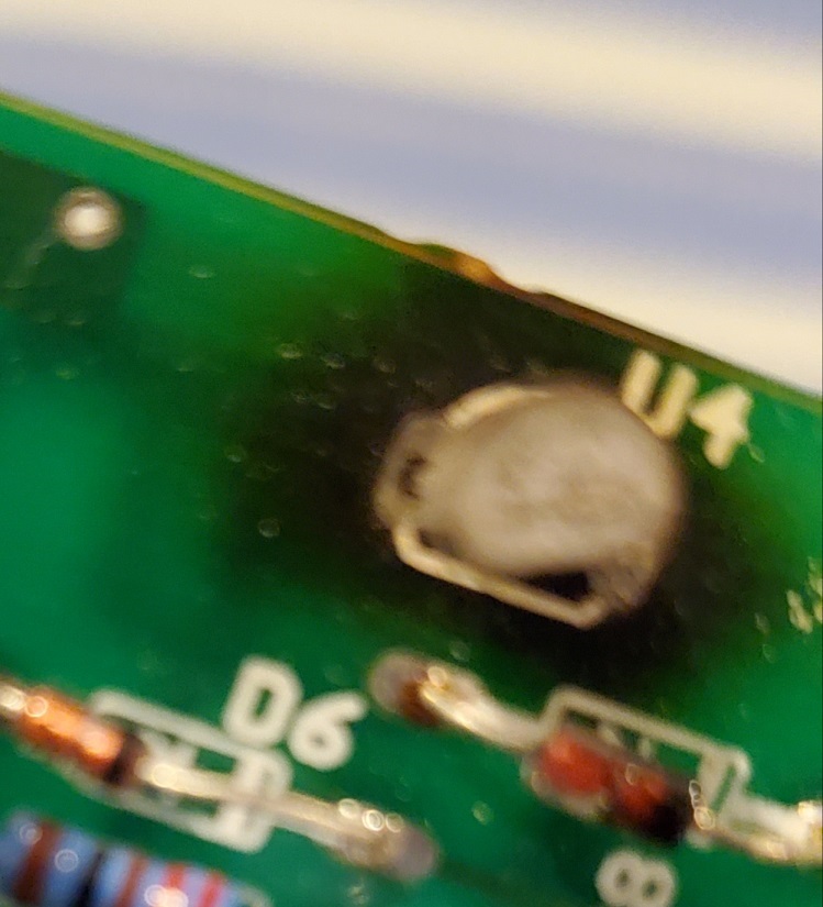
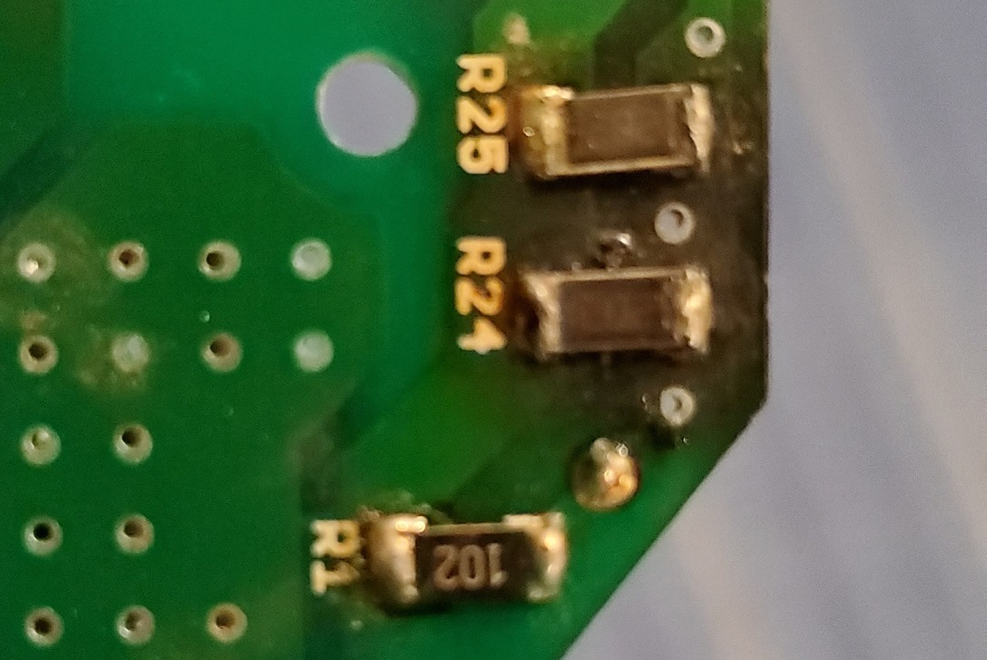
    The BaisHV circuit is suppose switch off once the power supply is on mode , but I have seen that R1 ,R24 and R25 have heating issue such that the pcb around them turn Black over a period of time. Also MOSFET U4 shorts out  after few months of use and usually it burns on start up. I have tested the circuit for standby mode for long period , the circuit never failed, the burning of components is only after the the ciruit has been over loaded few time. 

    The components are exactly as the BOM. The voltages at every point on the BaisHV circuit  is checked and is as per the design.

    I have Designed and built a PCB based on the TIDA-0065 .

    The photos will give an idea of the effect on the Bais HV circuit. this is on most board after use and after draw over 1.2 Amps , ie : total wattage exceeds 32 watt on watt meter connected to the input AC supply . if the boards are run at lower wattage of say 28 to 29 watt, board dont have this issue.

    I have kept the boards on standby for over 100 hours   and never seen the components burn, this test was performed to confirm the components can withstand prolong use of baisHv circuit.

  • Hi Prahu:

    my understanding is the output current of reference design is 1.2A. So if you want to output more than 1.2A, then maybe you need a FAN to cool the compoent on the board.

    can you try the TIDA-0065 to see whether the reference design has the same issue? 

  • Hi David

    The heating of main components (MOSFET and inductor etc) is  not a issue these are the components which should heat up on the drawing current. The baisHV is only used when the power supply is in low power mode.

    I need to know why the BaisHV circuit has this issue, it should switch off when the power supply is actually on and current is drawn, so this ciruit should not heat up and burn .

    I do not need more current, I am trying to understand why this happens.

    Also since the power supply can power can be driven to less than 30watts , I should be able to run upto 29.5watts with the designed circuit .

    The issue is not the actual circuit but the high voltage (power up and standby) power supply circuit, there is nothing except a DRV10983. So the current draw is very low.

    Regards

    Dinar

  • Hi Dinar:

    sorry for the delay reply.

    from the information you offer, I suggest you can do below test to find why there is over temperature issue on HVbias circuit.

    • when the ouput power is below 30W, for example at 25W, because there is no failure at HV bias circuit, at this conditon I suggest you can probe the current through U4 mosfet, suppose the current is I1.
    • Try to increase the output power to above 30W, for example at 35W, because there is failure at HVbias circuit, you can also probe the current through U4 mosfet, suppose the currnet is I2.

    the current I1 should be less than I2, because I2 makes U4 and resistor over temperature failure. At this time, you can try to increase the secondy turn of the inductor.

    The aim is to higher the voltage at signal MAG in the circuit, and always let HVbias bypass. 

    My guest is during over power conditon, HVbias charges VCC cap V12 all the time, and this makes the resistor and mosfet over temperature.

    Let me know whether it make sense.

  • Hi David

    Thank you for the reply, I did the tests you mentioned. following are the results.

    Set Up. current checked between the  output of the parallel resistor R24 and R25  and drain of the U4.

    1. Standby condition , DRV speed zero. Input power 2.0watts and current 5.1 to 5.4 mA this condition the output is 24Volts.

    2. Input power 12 watts , the current through U4 is 51.7mA, output voltage is 24V.

    3. input power 25 watts , the current through U4 is 44.0mA, output voltage is 24V.

    4.Input power 28 watts , current through U4 ias 44.2 mA, output voltage 24V.

    5. Input power 31.1 watts , current through U4 is 44.3mA, output is 24V.

    6. Input power 33 watts , current through U4 is 42.4 mA, output 24V.

    7.Input power 35 watts , current through U4 is 41 mA, output 24V.

    Shouldn't the MOSFET turn off as soon as the power supply turns on ? I mean at start up the Voltage between TP3 amd TP1 = 15.2 to 16.7 V, on  different power supplies,  when the power supply turns on the Voltage should be  3 volts above the start up voltage correct ? or Am I wrong?

    Thanks and Regards

    Dinar

  • Hi Dinar:

    your result suprises me. The current is lower at 33W (42.4mA) compare to 12W(51.7mA).But your experiment is at this condition, the mosfet and the reisistor have over temperature issue, this does not make sense.

    My understanding is current should be near zero after the power start up, from your test, it seems the circuit is always working.

    Please check the VCC on MAG, The voltage should be higher compare to the ovltage offered by Hvbias, For example 3V. So check you intuctor secondary winding ratio.

  • Hi David

    The transformer is is same as the Reference design from Wruth electronics. Can I use a 15v zener at the Gate drive to lower the output Voltage to say 13volt ?  since the UCC28180 can start from 11.5Volt VCC , this way I can confirm if the voltage from transformer as well , if it follows the actual design or just can not hold the voltage a current requirement of the circuit

    Regards

    Dinar

  • Hi Dinar:

    yes, please try it. thanks.

  • Hi David

    I have tried reducing the Gate voltage to 15v, but the the output  of Mosfet (vcc) does not cross 10.5V . it is below the VCC on Ucc28180, I have reduced the output to 14.2V at startup to confirm if that solves the issues of MOSFET not switching off,  but the same results, the Voltage at MAG is around 29Vdc but after R11 it is same as the output of MOSFET . ie Vcc at start up = Vcc after start up. There is still current draw through MOSFET as mentioned earlier in my post.

    Does voltage after R11 increase after the power supply starts up or is it same as the output of MOSFET?

  • Hi Dinar:

    the only way to let HVbias mosfet turn off is to let VCC higher than Mosfet Vg.

    Can you help try to decrease D7 from 18V to 13V, then higher the MAG votlage to at least 13V, then uses zero reisistor to replace R11?

    at this condition, there should not have any current through the HVbias mosfet after the power supply power on.

  • Hello

    I have tried the solution ,i dropped the Vg for U4 to 15volts so the output got down to 10.5Volts this is lower than the VCC needed by Ucc28180 to turn ON.  But I also tried controlling the output to 14.2 Volts , the volatge at MAG is 29 volt pulsed but after the 150 ohm resistor the voltage drops to same as the the output of U4.

    I am trying to to figure why the voltage follow the output of U4.

  • Hi Dinar:

    please try  replace R11 to be zero I listed in the past post. And Show the waveform to me.

    I need:VGS of the HVbias,Vmag,VCC together in one scope.

    thanks,

  • Hi

     will setup the power supply so I can get the wave forms, I have a 2 channel scope so it will be difficult to show all 3 together.

    You want the waveform with zero ohms connected or will the waveform with 150 Ohm do?

    I have 15 volt zener (Vgs)  which drops the U4 output to 10.5 volts will that work?

    do you need the wave forms with the power supply loaded with say 10 watt draw or just open power supply?

    Rgerads

    Dinar

  • Hi Dinar,

    you can compare the waveform with  zero and 150ohm on R11.

    with a 10W output is OK to me.

  • David Huang33 said:

    Hi Dinar,

    you can compare the waveform with  zero and 150ohm on R11.

    with a 10W output is OK to me.

    Hi David
    Thank you!! I have used your test procedure and figured out what was happening with the MAG voltage, I have designed the startup circuit and current through U4 drops from 5.2mA (at start up and standby condition) to 0.01mA at around 4 watts of output current draw. I have been trying to upload the waveforms you asked for but there is some issue with the upload page, I will try later again.
    Thank you very much for your time , it has been great help in understanding the issue.
    Thanks and Regards
    Dinar

  • Hi Dinar.

    Thanks for your update and happy to see that we have find the root cause. please allow me to close the post.

    By the way, can you send the wavefrom to me through email: wenbin-huang@ti.com   

    thanks.

  • Hi David

    Yes will send the wave forms on the email.

    Thanks and Regards

    Dinar

  • Hi Dinar,

    the post has been closed,please do not reply it. thanks.