This thread has been locked.

If you have a related question, please click the "Ask a related question" button in the top right corner. The newly created question will be automatically linked to this question.

UC2526: Regulated PWM Output

Part Number: UC2526
Other Parts Discussed in Thread: LM358


Dear Sir,

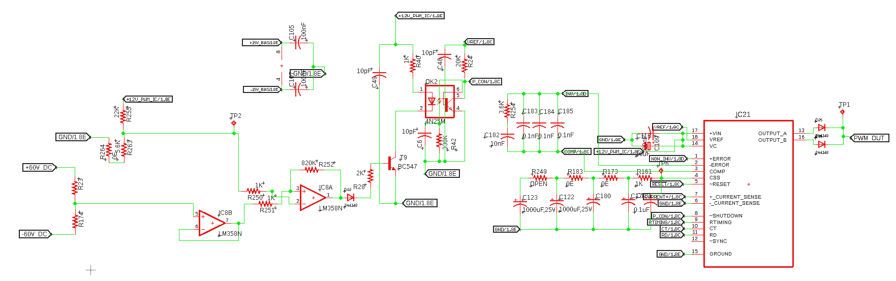
We are using UC2526 to control the Buck output voltage as per the attached schematic.

Pin no: 1 of UC2526 error amplifier is set to 5V as a fixed reference.
Pin no: 2 of UC2526 error amplifier is connected to 4N35 Collector (will vary based on feedback from 0 to 5V).
we are using Type II Compensator to stabilize to loop

External feed back input signal pass through LM358, BC547 and 4N35 to the Pin no: 2 of UC2526 error amplifier.
Output signal from 4N35 output will be square wave (not pure analog signal)

will this flow of schematic attached will adjust the duty cycle to regulate the output voltage ??.
Please verify the schematic and suggets the your Valued inputs to achive the regulated PWM.

Regards

Murthy

  • Hi Murthy,

    The schematic appears to be incomplete and I cant read it clearly from the post. Can you post it as a PDF. What is you end application?

    Thanks

    Peter

  • Dear Sir,

    please find the attached Schematic

    for industrial use

    Regards
    Murthy

    Test Schematic.pdf

  • Hi Murthy,

    Thanks for the pdf schematic, from what I can see there are no components on the CT or RD pins of the controller so it will not oscillate and there will be no PWM output.

    Have you looked at the UCC28C4x family of devices they have PSPICE and TINA models that you can use to simulate your circuit. They have variants that do 50% or 100% duty cycle and are only 8 pin devices.

    Regards

    Peter

  • Dear Sir,

    Please find the attached schematic.1057.Test Schematic.pdf


    I have checked UCC28C4x IC TINA model.

    Please Suggest if any changes required. I need to control step down chopper

  • Hi Murthy,

    When you say you want to design a step down chopper do you mean buck stage?

    The TI Webench tool will give you a complete schematic for a buck circuit.

    https://webench.ti.com/

    Regards

    Peter

  • Hi Peter,

    Can you share your mail ID. 

    I will share schematic with you.

    As you Know i am Using PWM IC UC2526 with reference previous posts

    Problem No 1: My PWM Pulses are missing after certain time period. Because i am using reset pin for my closed loop control using Optocoupler. But i don't what will be the adverse effect of missing PWM pulses on Buck Converter especially Inductor. I Want to resolve this problem.so that's why i am approaching you.By using this my output regulation is good.i testes the system by continuously running for 4 hours.Nothing is happened. But i heard sound from inductor apart from switching noise from starting till 4 Hours. Sounding like tak...after 2 or 3 sec....tak....after 2 or 3 sec....tak....I think these is happened because of missing pulses.Please confirm that this is not a big problem from experts in Power Electronics people from texas instruments.

    Actions from my side: I tried  by connecting optocoupler output to Inverting PIN and Comp Pin of UC2526. I am not getting PWM pulses output from UC2526 in closed loop.i think this is happened because of Compensation.if possible can you share closed loop control of Buck Converter application circuit using UC2526. it would be helpful. 

    I Have some queries

    Question No:1 Comparator output connected 0 to 5V through optocoupler can be connected Invertering pin UC2526.

    Here i am attaching missing PWM pulses .JPG

    Hope you will help in solving my problem

    Regards 

    Murthy

  • Hi Murthy,

    I am closing this post as we have moved support to email, please respond to my last email so we continue to work on this problem.

    Regards

    Peter

  • Dear Sir,

    I replied to your last mail with PDF document & Schematic 

    Regards

    Murthy

  • Hi Murthy,

    Since we are communicating by email I am going to close this post.

    Regards

    Peter