This thread has been locked.

If you have a related question, please click the "Ask a related question" button in the top right corner. The newly created question will be automatically linked to this question.

TPS7A4701-EP: Will not regulate.

Part Number: TPS7A4701-EP

I am using p/n TPS7A4701RGWR to generate 8V from a V_SUPPLY that varies from 10-14V & is 12.5Vnom.

The TPS7A4701 regulates as follows;

Vout = 7.1V a Vin = 10V, 

Vout = 5.75V a Vin = 12.5V, 

Vout = 5.5V a Vin = 14V, 

Iout is around 10mA.

The output increases with additional load current

Any ideas what might be going on with this regulator?TPS7A4701.pdf

  • Hi Steve,

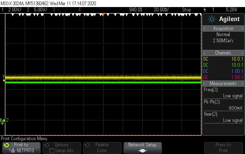
    What you describe is very strange behavior, can you provide some scope shots showing the input, output, and enable voltages? If it is possible to include the load current that could also be very helpful though we understand that it's often difficult to add a current probe. This information should help us to better understand what is happening. 

  • Channel 1 is the output = 5.65V

    Channel 2 is the input = 12.95V

    The enable pin is tied directly to the Input pins a looks just like Channel 2

    I'm not sure what you mean by adding in a current probe.

    The load current is just 14 10K pull up resistors 

  • I shorted the output and the TPS7A4701 goes into thermal overload and shuts down as expected.

    I shorted additional xPxV pins to ground and the output does increase, just not the full amount that is expected based on which one is shorted..

  • Clarification on the load current.  The TPS7A4701 is generating the 8V for the 10K pullups, not trying to sink the current from them.

  • Does this regulator require a minimum load current?  It is behaving a little better if I add a 200mA load to its output.

  • Hi Steve,

    Thanks for the additional information on the loads and the behavior with increased load. This device does not have a minimum load requirement, in fact the EC table actually specs the accuracy at 2.5% all the way down to 0mA. 

    Since you have many loads coming off your 8V rail where in the layout are you connecting the SENSE connection and where is that relative to where you are measuring your scope shots from? 

  • The Sense line is connected directly to C55 & that is where all of my measurements are being taken.  B55 is very close (~0.1") from pin20 of the TPS7A4701.

  • Hi Steve,

    That description of the layout sounds good. Given all the information you've provided, I cannot think of a reason for the behaviors you are see and I'm concerned that maybe the device was exposed to some sort of abs max event which may have damaged the device. In this situation I'd suggest the following (assuming you haven't already done so):

    1. Perform A-B-A swap: Take the suspected bad part off the failing PCB and swap it with a good part on a known working board. Also swap that good part so it is now on what was the failing PCB. See if the failure follows the part or if it follows the PCB. 
      1. I expect it to follow the part but in this situation we want to be certain so we can debug the right thing
    2. Perform Spike Check: Use scope probes connected to Vin and Vout and look for any abs max violations on these pins. In particular make sure that neither Vin or Vout exceeds 36V and make sure that Vout is not higher than Vin by more than 400mV. 
      1. Since your loads to this LDO all have a 10k resistor in series with them this should limit the affect of any of the LDO's load transients, so I would focus on the system/rail startup and shutdown sequences and any transient events for that input rail including other transients due to loads connected to the same input power rail. 
    3. If #1 shows that it follows the part and #2 shows no abs max violations then I'd evaluate the possibility that the device was exposed to an ESD event which exceeds the datasheet limits. 

    Let me know if you have any questions on these tests. 

  • 1. I replaced a failing regulator from one in stock and it is behaving the same way.  Still failing to regulate

    2. I am not seeing any voltage spikes during power up.  When I preformed step 1 above I brought the supply voltage up very slowly.

    3. Replaced regulator still fails.

    Any other ideas?

  • A brief update on this issue.

    I replaced the TPS7A4701 with a TPS7A4700 and am getting the same result.

    The TPS7A4701 / TPS7A4700 output 6.2V when they should be outputting 8.0V

    I also tried to configure the TPS7A4701 to run in adjustable mode instead of ANY-OUT mode.

    I cut the traces going to pins 5 & 11 and connected a resistor divider from the output voltage to ground to feed the SENSE/FB pin.

    R1=47.5K & R2=10K.  This should result in Vout=8.07V.  Instead, Vout=7.8V

    This improved the TPS7A4701 performance but its output still also varies with the input voltage.

    Any help on this would be greatly appreciated.

  • Hi Steve,

    Sorry for the delay. I'm a little confused, can you be more specific is the new part on the original failing board working? Did the Original failing part continue to fail on the new working board?

  • Kyle,
    I have no working boards.

    I placed a new part on a failing board and it still fails.

    Steve

  • Hi Steve,

    This makes me very suspicious that something is going on at the PCB given that you replace the part and get the exact same behavior and there are no abs max violations or reverse current events happening since this also seems to indicate it isn't an ESD issue since you are seeing the same behavior on multiple parts. 

    One possible cause could be leakage current caused by the PCB. Has the board been very thoroughly cleaned? Sometime after assembly of a board there can be residue left on the PCB surface which can create leakage from high impedance nodes to an unintended voltage/pin. Examples of high impedance nodes that could cause the output to be incorrect are the NR pin and the Any-Out pins (pins 4-12). This could explain the improvement you saw by cutting the traces to the Any-Out pins and installing an external resistor divider. If the NR pin still had leakage to GND (or to any low voltage) that could drag down the internal reference and result in an output voltage that is too low. 

  • Kyle,

    I already suspected contamination and sent a board through our Aqueous PCB Cleaning Machine.

    This made no difference.  The 8V output reads 6.2V

    Can I ship you a board for evaluation?

    Steve

  • Hi Steve,

    At this point is seems like it would be good for you to start the customer return process. Here is a link outlining how to initiate that process based on how/where you purchased the devices for your application.

    We may get to the point where evaluating a board in our labs makes sense but first it would be good to verify that the parts are not damaged and working properly. Part of the return process runs the returns through the production test to make sure it is still operating the same way we'd expect it to when it was shipped out from factory. 

    I want to be open with you concerning our resources being stretched pretty thin right now due to the precautions being taken concerning the Coronavirus, so it may take longer than usual to complete our evaluation but we are working through these things as quickly as we are able.   

    I'm sorry we weren't able to resolve this more quickly. 

  • Kyle,

    We have not purchased production quantities of this regulator recently.  We use this regulator on other designs & they are working fine on those designs.

    Also, as part of troubleshooting this issue I purchased a small quantity of these from DigiKey (a second trusted source) along with some TPS7A4700 regulators which are also failing.

    I'm pretty sure there is something in our design that is rendering the 4701 regulator unstable.  I'm just not sure what it could be.

    It would be really good to understand what the underlying issue is.

    At this point I am designing the TPS7A4701 out and replacing it with a different linear regulator.

    Steve

  • Hi Steve,

    Can you confirm that you have a ground plane directly underneath the LDO circuitry?
    This would be the ground of the LDO, and the plane would be in the first inner layer of the PCB underneath the LDO circuitry.
    In particular the EN and FB pins should have a ground directly underneath them.

    Thanks,

    - Stephen

  • Hi Stephen,

    Thanks for weighing on this.

    Yes, the TPS7A4701 circuit is on the top layer of the board and the layer directly below it is a solid ground plane.

    This ground plane extends well beyond the EN & FB pins of the 4701 regulator.

    Steve