This thread has been locked.

If you have a related question, please click the "Ask a related question" button in the top right corner. The newly created question will be automatically linked to this question.

[FAQ] UCC27712-Q1: Why should I replace 3-phase bridge drivers with half-bridge drivers in automotive AC compressor modules?

Part Number: UCC27712-Q1

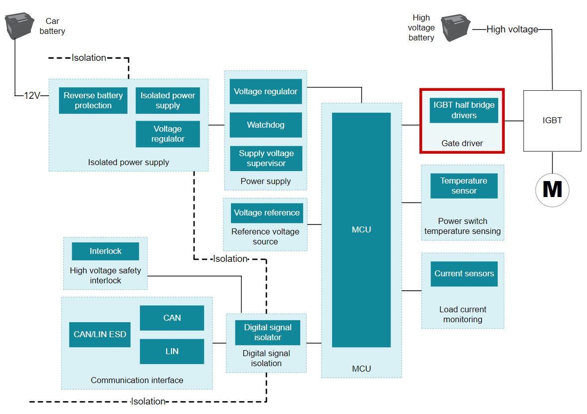
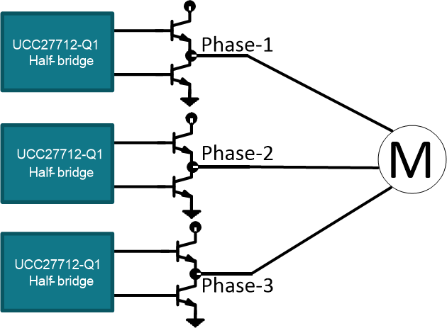
I am currently using 3-phase bridge drivers for the IGBTs of the inverter stage of a BLDC motor.

Why should I consider a gate driver to replace the 3-phase bridge driver in my existing solution? What are some performance advantages of the half-bridge gate drivers over my current solution? 

  • Why should I replace 3-phase bridge drivers with half-bridge drivers in automotive AC compressor modules?

    High-voltage 3-phase BLDC motors are used to drive the AC compressor in high-voltage HEV/EV. HVAC compressors, which can require 10 kW of power, are second only to traction motors in terms of power consumption.

    Figure 1 shows a typical AC compressor module block diagram with IGBTs as the inverter stage to drive the 3-phase BLDC motor. An inverter stage consists of three pairs of high-side and low-side IGBTs configured in half-bridge topology.

    Figure 1: Block diagram of an automotive high voltage HVAC compressor module

    As shown in Figure 2, designers have the choice of using 3-phase bridge drivers IC’s to drive the IGBT’s of the inverter stage. However, because of their low drive strength of <500 mA, 3-phase bridge driver solutions typically require additional buffers to act as a current booster. This means additional components, which translates into additional cost, system PCB size increase and performance degradation (EMI risks and increased propagation delays) of the overall system as a result of parasitics from a non-ideal PCB layout.

    Figure 2: Driving the inverter stage with 3-phase gate drivers

    To help minimize switching losses from the IGBTs and reduce EMI for higher system efficiency, designers have the choice of using half-bridge gate drivers to drive each phase of the inverter stage instead. That is, the 3-phase bridge drivers depicted in Figure 2 are increasingly being replaced with half-bridge drivers such as UCC27712-Q1 as shown in Figure 3.

    Figure 3: Driving the inverter stage with three half-bridge gate drivers

    The following are the reasons for using TI half-bridge drivers to drive the IGBTs:

    • From a gate driver standpoint, EMI is often associated with overshoot at the gate. The configuration shown in Figure 2 leads to complex PCB layout including long PCB traces from the 3-phase driver switch node pin to the IGBTs, which could cause more EMI challenges. UCC27712-Q1 based approach shown in Figure 3 allows removal of extra components, reduces the complexity of the PCB layout because the driver IC can be placed very close to the IGBTs while also confining the switch node to minimal area. All this leads to less challenges with EMI.
    • Does not require external booster stage to amplify the gate drive current as the IC can achieve 1.8A/2.8-A source and sink current.
    • Interlock and dead time functions protect half-bridges from shoot-through by preventing both outputs from being turned on simultaneously.
    • Wide VDD range 22V offers sufficient margin to effectively drive the IGBTs.
    • The IC is in a 6.0-mm x 4.9-mm package saving significant PCB area as opposed to 3-phase bridge drivers where the ICs often have bulky dimensions (17.9 mm x 10.3 mm in some cases). This smaller size and reduced number of ICs and associated passives components leads to smaller PCB area needed for the circuits to drive IGBTs.

    Table 1 below highlights some of the key performance advantages of the UCC27712-Q1 half-bridge gate driver over some 3-phase bridge drivers.

    UCC27712-Q1

    Common 3-phase

    bridge drivers

    Peak output current (A)

    >1

    <0.5

    Rise time (ns)

    <20

    >100

    Fall time (ns)

    <20

    >50

    Prop delay (ns)

    <110

    >500

    Iq (uA)

    <300

    >2500

    Operating temperature range (C)

    Down to -65C

    Limited to -55C Abs max

    Package group

    SOIC | 8

    SOIC | 28


    Table 1: Performance advantages of the UCC27712-Q1

    References: