


Other Parts Discussed in Thread: UC2843A-Q1, TPS92692-Q1, TPS92691-Q1
How can I use current mode PWM controllers or LED drivers in an automotive high-voltage contactor economizer?
A high-voltage electric battery in HEV/EVs is used to power the traction inverter and other high-voltage loads such as the AC compressor. To connect the battery to the loads, the battery power lines are routed through electronically controlled, high-voltage switches called contactors.
Figure 1 shows a typical high-power vehicle boardnet with contactors in the battery disconnect unit (BDU) and power distribution box (PDB).
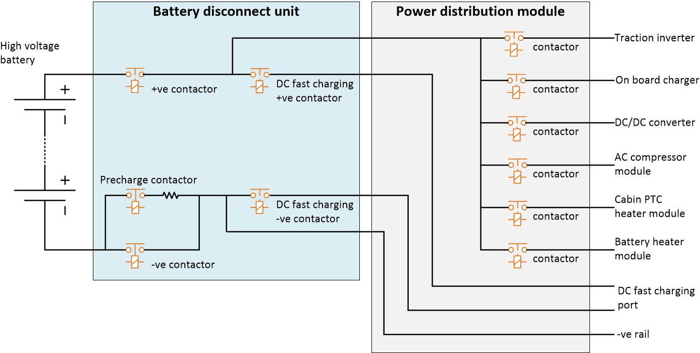
Figure 1: Typical high-voltage power boardnet with contactors in HEV/EVs
The high-voltage contactor is electronically controlled by powering a low-voltage coil inside the contactor. The low-voltage contactor control circuit, called the economizer, drives this low-voltage coil inside the contactor and is powered by the low-voltage bus in the vehicle; for example 12-V bus. Further, the control signals for switching the high-voltage contactors on or off are generated by control modules such as the vehicle control unit (VCU) or the HVAC control module in the vehicle.
Figure 2 shows the profile of the current in the low-voltage coil. This current profile, called a pull-in-and-hold profile; when the contactor is first switched on, the current in the coil is initially high. This is the pull-in current, represented by ipull in Figure 2. The pull-in current is followed by constant-hold current, represented by ihold in Figure 2, for the remainder of time that contactor is on. The pull-in current ensures that the contact is made while the hold current ensures the contacts remain in place.

Figure 2: Pull and hold current in contactor
As shown in Figure 2, one of the key functions of an economizer is to regulate the current in the low-voltage control coil. Texas Instruments wide portfolio of current mode PWM controllers that includes devices such as the UC2843A-Q1 and UCC28C43-Q1 and LED drivers such as TPS92691-Q1 and TPS92692-Q1 are well suited to regulate the current in the low-voltage coil.
The current PWM controllers feature a simple yet effective control architecture. With only eight pins, the UC2843A-Q1 and UCC28C43-Q1 can drive MOSFET gates directly. Furthermore, these industry-proven devices offer a flexible and scalable controller solution for the high-voltage to low-voltage conversion and can also support wide-input range applications. Figure 3 shows a circuit concept for an economizer with the PWM controller.
The LED drivers are fixed-frequency current regulators and hence integrate the current control feature. Both the TPS92691-Q1 and TPS92692-Q1 have an input pin that is used to set the current set point. Further, the TPS92692-Q1 integrates spread spectrum which helps with EMI mitigation. Figure 4 shows a circuit concept for economizer with a LED driver.

Figure 3: Current mode PWM controller shown in contactor economizers

Figure 4: LED driver shown in contactor economizers
The economizers in Figure 3 and Figure 4 also include power supply and current set point generator blocks. These blocks can be easily realized by using Texas Instruments wide portfolio of LDOs, analog multiplexers, operational amplifiers and comparators.
References:
-
Review the battery disconnect unit or power distribution box interactive system block diagram
-
Learn more about the UC2843A-Q1 and UCC28C43-Q1
Learn more about TPS92691-Q1 and TPS92692-Q1