This thread has been locked.

If you have a related question, please click the "Ask a related question" button in the top right corner. The newly created question will be automatically linked to this question.

BQ76940: Power supply and REGSRC pin

Other Parts Discussed in Thread: TMS320F28335, BQ76940, BQ78350, EV2400, BQ76930

Hi, 

I would like to use BQ76940 for 12 cell battery with:
-  Cell nominal voltage 4.2V, Pack nominal voltage 48V (for 12 cell).
- Cell maximum voltage is 4.7V and Pack maximum voltage is 56.4V.
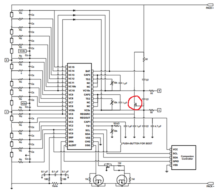
But in the datasheet, I see that the voltage range for REGSRC pin is -0.3 - 36V. And the datasheet show can use a FET to reducing the voltage.
Can you explain to me:
How the FET can reducing tho voltage?
How can I control this mosfet to make the voltage supply for REGSRC with range   -0.3 - 36V  ? 
How can I calculate the current support for REGSRC and confident the voltage in range -0.3 - 36V  ? 
Thank you very much for your support!
  • 1. How the FET can reducing tho voltage?

    The FET circled is a source follower. You might search your favorite circuit referece for 'source follower' or 'common drain' amplifier.  As an amplifier it will have a high input impedance, a gain of 1 and can supply as much current as the FET allows.  In its use as pictured here Vregsrc  ~= Vvc5x - Vgsth  There will be some REGSRC voltage variation with load due to the Vgs for various currents of the FET.

    2. How can I control this mosfet to make the voltage supply for REGSRC with range   -0.3 - 36V  ? 

    The MOSFET will operate on its own as pictured and described above.  Connected as shown above referenced to VC5X with 5 cells,  a range of 3 to 4 V/cell,  and a Vgsth of 2V: VC5X would vary from 15 to 20V. REGSRC would vary from ~ 13 to 18V.

    You may want extra components around the FET: A resistor in the gate may provide ESD isolation.  A resistor in the drain will drop some voltage to reduce power in the transistor. A diode-resistor parallel combination in either the source or drain will block discharge of the REGSRC capacitor during short circuit.  In the EVM the diode-resistor is in the source, but this does drop the REGSRC voltage under load.  A resistor in the source will also keep some power dissipation out of the IC at high load but will drop the REGSRC voltage.  The EVM has a 100 ohm resistor as a current measurement shunt, it is not needed and may not be desirable.

    In your 12 cell battery, assuming a voltage drop to 3V/cell, you would have VC5X filtered from the 4th cell (see the datasheet "Cell Connections..." table).  Your VC5X voltage range may be 12V min, 16.8 nominal and 18.8 maximum.  REGSRC voltage would be the Vgsth of your selected FET below these, if Vgsth is ~ 2V you may have 10 to 16.8V.  Since the FET drive voltages are regulated from REGSRC, the FET drive voltages will drop noticeably at the low end.  You would want the diode discharge prevention circuit in the drain. If the lower gate drive at low voltage is OK you might do this.   

    If the low gate voltage is undesired, the next option would be to consider using the gate referenced to VC10X which would be your 8th cell.  With the assumptions above, VC10X would vary from 24 to 37.6V  REGSRC would be ~ Vgsth below or ~ 22 to 35.6V.  This is mostly above the recommended operating range and very close to abs max. 

    VC5X and VC10X are attractive references for the source follower since they are already available as heavily filtered voltages.  You may choose to filter perhaps the 5th or 6th cell to provide a reference to generate the REGSRC voltage.  It does require another R & C but may position the REGSRC range in a more desirable range.  Choose a suitable time constant for the filter, perhaps in the 1 - 5 ms range.  The time constant desired will vary with the system behavior.  VC5X, and VC10X will have a specific voltage profile depending on the loaded cell voltages.  A  separately filtered cell reference will also droop with battery load but can be more easily controlled with its separate R & C.  If your system pulls the battery voltage low for extended times without tripping the SCD or OCD fault but less than the UV fault, select an appropriate time constant for the separate R-C filter.

    Another option is to provide a 15 to 18V supply for REGSRC, but this may add more quiescent current, components and cost to the system.

    3. How can I calculate the current support for REGSRC and confident the voltage in range -0.3 - 36V  ? 

    The REGSRC current will be made up of the internal supply current, the FET output drive current, and the REGOUT current. The internal supply current is shown in the datasheet, ICC_REGSRC.  The FET drive current should normally be ~ 12 uA for each FET depending on the gate-source resistance selected for the power FETs. The REGOUT current will depend on the MCU, the bq769x0 datasheet shows output voltage for up to 20 mA load on REGOUT.  Select a FET which will carry the load and handle the power with the load expected and at the temperature expected for the board.  For the voltage, see above, also consider the voltage drop across any resistors included in the current path.

  • Thank you very much for your help!

    I will check it again to understand clearly.

    Best regards,

  • Dear WM5295,

    Your support take me understand  about IC design more clearly. 

    Now I still get a problem. I hope that you can help me understand more clearly.

    1. What is target of 2 Mosfets which connect to DSG and CHG pín ? Can I remove them?

    2. In my application, I would like to measure the voltage of each cell and then report to DSP TMS320F28335 by I2C communication. Which IC is most suitable for my application ?

    Thank you very much for your help! 

    Best Regards,

  • Lithium ion batteries should only be used in their safe operating range.  The charger or system load should do this of course, but the funciton of many battery management ICs or BMS systems is to provide a level of protection if something goes wrong or some unexpected condition occurs.  The MOSFET connected to the DSG pin can be turned off to prevent discharge of the battery and the MOSFET connected to the CHG pin can be turned off to prevent charge current into the battery.  These FETs can be controlled by the MCU through the bq76940, or by the bq76940 directly.  So for example a system should stop discharge of the battery before its voltage is too low.  If the system does not stop discharge, the MCU conneced to the bq76940 can recognize the low voltage and turn off the DSG output.  If the MCU does not turn off the DSG, the bq76940 can turn off the DSG at the threshold level previously set in its register by the MCU (there is a default, see the datasheet).  The bq76940 will also turn off the DSG in case of a short circuit or over current which may happen faster than the MCU could recognize or react.

    Whether you can remove the charge and discharge FETs will depend on your system design.  It is generally accepted that a battery system has FETs some place to prevent over discharge and over charge, where those are located will depend on the system.  With a removable battery they are typically located in the battery since the terminals are accessible when the battery is removed and may be subject to unintended connections.  Placement of the FETs also involves consideration of communication needed.  The low side switching shown is relatively easy to implement and low cost, but can complicate ground referenced communication if that is needed. Be sure to follow established design practices for your industry and consult your safety engineers and applicable regulations for your equipment.

    The bq76940 will convert the cell voltages (if enabled by the MCU) and make these available in registers.  It will also provide the safety functions mentioned above and further described in the datasheet.

    The bq78350 is an MCU with a battery management system implemented configured by its parameters.  It will provide further voltage offset calibration for the cell voltage beyond the factory calibration of the bq76940.  It will make cell voltages available in a register set (command set) accessed by SMBus.  It provides battery protection, recovery and gauging functions.

    A separate MCU such as the TMS320F28335 would seem suitable to interface to either the bq76940 or bq78350.  When not using the bq78350 and connecting directly to the bq76940 the firmware will need to provide the setup and fault recovery for the bq76940 as well as any special behavior you wish.  I do not know the best MCU, you would of course need to consider the code space and peripherals you need in your system.  It would be best to inquire with the TMS320 experts for guidance.

  • Dear Mr/Ms WM5295,

    Thank you very much!

    I have understand clearly by your help.

    I will consider more about host controller.

    One more time, thank you very much!

    Best regards,

  • Dear WM5295,

    In my design, I don't use CHG and DSG and REGOUT also.

    Do I need supply REGSRC? 

    I have read this one in the application note. But I'm not sure:

    "If I will not use the REGOUT voltage from the AFE. Do I still need to supply REGSRC and a capacitor on REGOUT?
    oYes, REGSRC and REGOUT are required. REGSRC powers the FET drivers, and REGOUT powers assorted internal circuitry, including the communication buffers and coulomb counta capacitor value on the low side of the recommended range should be fine. The REGSRC pin should have an approximately 1-µF capacitorer. If you are not using the REGOUT voltage externally."
    Thank you very much!
  • Yes, you will still need REGSRC. REGSRC provides the power for REGOUT and both are needed for internal operation.
  • Yes, Thank you very much!

  • Dear WM5295 and everyone,

    I have checked User’s guide (slvu925b) and datasheet (SLUSBK2E) also, but I still have not understood some points. I hope that you can explain to me:

    1. Why the Ground (GND) connect to capacitor C9 and C19 also? (Figure 27, slvu925b)

    2. In the datasheet, the power support to BQ76940: Pin 10 (VC5x) connect to point A which is connected at the top off cell 5. (Figure 8-3, SLUSBK2E). But in the User’s guide: Pin 10 (VC5x) connect to point VC5x which is connect to capacitor C8 and C14 also.

    Is there any difference when connect pin 10 of bq76940 to the two point?

  • When I connect EV2400 EVM Interface Board to bq76940 in the circuit. I get the problem as:

    I have connected circuit to a battery 12cell 45V. Then I check all input voltage and output voltage as:

    How can I fix the problem?

  • 1. C9 and C19 both connect to ground to provide filtering for the inputs while avoiding C0 from being pushed below VSS during sudden load on the battery.  A typical optional configuration would be to connect the bottom of C19 to VC0, but then when C1 drops, VC0 is pushed below VSS.  The part is designed to tolerate some of this as the same structure exists at VC5B and VC10B, but it is best to avoid it with this capacitor configuraiton

    2. This confusion happens because the pin s are on different sides of the part.  The datasheet uses a physical pin representation on the symbol so the point "A" and "B" avoid wires crossing over circuitry to go around the part.  On the EVM the symbol the pins are more logically ordered but the power pins are still on the other side of the part.  This and the page size of the EVM put the input filter on one page (figure 27) and the power filter on another page (figure 28).  C5 (cell 5) connects to VC5X through the Rf resistor R59.  (R62 is in series as a current measurement shunt, the math is actually easier if measuring across the 1k R59).  Pin 10 of the bq76940 is VC5X, when cell 5 (net C5) is connected, VC5X will be powered.  The filter resistor(s) Rf are important, operation without these resistors either open or shorted may result in damage.

    For the GUI operation: The voltages seem reasonable.   Since REGOUT is 3.3V it seems you have a bq76940-02, bq76940-03 or bq76940-06. 

    • If the part is on the EVM be sure the gauge is disconnected
    • If the part is on the EVM be sure the 4 pin connector is connected to the I2C connector
    • The EV2400 provides pull ups for I2C, the EVM SDA & SCL pull up jumpers should not matter, typically they might be removed.
    • Be sure the 4 pin cable connects to the "I2C" connection of the EV2400
    • If using your own board be sure your MCU is disconnected or reset to leave the I2C bus idle
    • If you are using the bq76940, its address is 0x18, change the address in the box in the right top area of the evaluation software window.
    • The bottom area of the evaluation software should show a status to show if the part acks or nacks, from the message
    • You might inspect the SDA & SCL with a scope to look for signal quality and perhaps REGOUT be sure the voltage is remaining on after boot and during the read attempt.
    • If you have had construct a special cable, be sure the SDA & SCL lines are not reversed and there is a good ground reference.


  • Dear WM5295,

    Yes, The IC in my circuit is BQ76940-03.

    Now I can connect I2C from computer to the circuit.

    This is SDA and SCL signal: 

    But I still can not measure the voltage of battery (15 cell)

    All the input voltage (VC10x, VC5x,... ) are same last time. 

    I have check circuit, but I have not find the problem.

    Which one I need to check to fix this problem?

    Thank you very much!

  • The waveform looks reasonable and it seems from the software screen the part is now communicating. It shows a DEV_XD or XREADY status bit. If CAP1 and CAP2 both have normal voltage click the "clear faults" button, then "update display" or select the "scan" box. The XREADY fault will occur if the part is booted before the upper cells are connected, if CAP2 is shorted in operation (by probing for instance), or if excessive system noise causes sufficient communication loss so that the watchdog-type function sets the fault.
  • Sorry, you said bq76940. CAP1, CAP2, CAP3 must all be ~ 3.3V to clear XREADY. Your voltages show these present, you should only need to clear the fault to proceed.
  • Dear WM9625,

    Thank you very much for your support.

    I have check all the voltage input and output. But I have not find any fault.

    REGOUT = 3.3V and ALERT = 3.3V. 

    How about IC? Maybe IC get problem. 

    Or the IC change to SHIP mode? But when I push PUSH-BUTTON, computer still can not read the voltage.

  • Dear WM5295,

    I have check circuit several time and I see the problem:

    The voltage VC7-Vss =18.6 V.   The voltage VC8-Vss = 26.6V.    So the voltage VC8-VC7 = 8V  >  7.2V

    In the datasheet, the maximum voltage of one cell is 7.2 V

    I have fix this problem, now VC7-Vss =23.2 V  and  The voltage VC8-Vss = 26.6V.   But computer still can not measure the voltage of any cell even output voltage: REGOUT = 3.3V and ALERT = 3.3V.

    Maybe after the voltae bigger than 7.2V, BQ76940 was fail and then  it can’t work?

    Is there any problem if the voltage of cell is bigger than 7.2V ?

  • Dear WM5295,

    I have fix some problem in the circuit. And I get the voltage only of first 5 cell

    Also I see a problem is the bit DEV X is high. I have check the datasheet, which show that this is Internal chip fault detected. That mean bq76940 fault?

    How can I fix this Problem?

  • In BQ76940 Evaluation softwave. I have click to Clear Fault. But The softwave can not clear DIEV X bit and still measure first 5 cell
  • I have read the User's guide and I get that:

    1.12 Why is the DEVICE_XREADY bit high on my part and it cannot be cleared?
    For the bq76930 and bq76940 it typically indicates that the voltage on the bottom cell group is adequate, but one of the upper cell groups’ supply voltage is below V SHUT. Raise all cell group supply voltages above VPORA and clear the status bit. Another possibility is that the part has been damaged.

    But in my circuit, the voltage of every cell is bigger than 3.6V. 

  • There are several posts for this one reply:

    The voltage VC7-Vss =18.6 V.   The voltage VC8-Vss = 26.6V.

    This would be a large difference in VC8-VC7, 8V.  There are 2 limits for each input, a differential input and a single ended input.  The differential input limit is 9V, so this would be OK.  The single ended input limit is staggered for most numbered cells at 7.2V/cell with respect to the group reference.  For cells 7 & 8 the group reference is VC5X.  If your VC5X is still 14V as the earlier report, VC7-VC5X would be 4.6V, well within the 14.4V limit.  VC8-VC5X would be 12.6V, within its 21.6V limit.

    The voltages you describe do not sound damaging as I understand them, but if the part was damaged by abnormal voltages, it may not work after voltages are returned to normal.  Or after abnormal voltages the part may work fine, but you may not want to trust it for long term operation if you know it was overstressed.

    From the screen capture yesterday, 4/19, DEV_XRDY is set along with some other faults, and 5 cells show voltage.  The XREADY indicates a communication problem with the cell voltages as you can see.  Since the bottom group cells (1-5) show a voltage, the problem is likely with the top group.  Check that CAP3 is present at @ 3.3V with respect to VC10X.  You may need to check it with an oscilloscope to be sure it is not dropping out and coming back.  If all CAPx are 3.3V (across the capacitor = pin to local reference) the part will normally allow XREADY to be cleared.  If you know abnormal voltages were applied perhaps the part has been damaged.

    The voltage reported on cells 1-5 seems slightly unusual.  If you have 12 cells we would recommend shorting cell 4, 9 and 14 (from the datasheet table 8-3),  Cell 4 would normally read near 0 or the offset voltage (46 mV shown).  Similarly cell 5 reports ~ 800mV higher than cell 3 and cell 1 is ~800 mV lower than cell 2.  If you are using a resistive cell simulator these voltages usually match better.  If you are using cells, results will vary with the cell of course.  

    If using a board setup for 15 cells for a simple 12 cell test, be sure to short the inputs at the board connector.  This will short the appropriate cell simulator resistor also, or if using cells the cell connects to the common shorted pin pair.  When connecting to an external cell simulator you can short the VCn pins only and not connect to the unused input pin.  If shorting both VCn and the appropriate cell pins, the filter resistors of the shorted inputs will be paralleled and the resistance will be lower.  A 45 V 12 cell battery should give you ~ 3.75V/cell.  Also I note in your earlier report that the power voltages were very different:  10.2 on the top group, 18.9 on the middle, and 14V on the bottom.  While these are all above VSHUT and the part should be able to work, it is odd with a 12 cell setup that they are so different.  Please check your simulated cell voltages or cells.  

    You post earlier today: "But in my circuit, the voltage of every cell is bigger than 3.6V."

    Yes, see above.  The voltage on the cell should show up on the appropriate VCn and VCn-1 pins.  With 12 cells you should have 4 cells per group, so BAT-VC10X ~= VC10X - VC5X ~= VC5X - VSS ~= 15V.  You should see CAP3 - VC10, CAP2-VC5X and CAP1-VSS all ~ 3.3V and stable.   If the voltages look odd, correct the problem.

    Be sure that there is a thermistor or resistance connected for each:  TS3 to VC10X, TS2 to VC5X, and TS1 to VSS.  If TS3 or TS2 is pulled down to VSS the part may not start up, I expected this prevented CAP3 voltage rather than DEV_XREADY alone.

    If all voltages look normal it may be that the part has been damaged, or if you can measure abnormal voltage due to abnormal current into the IC pins, the device is likely damaged and will need to be replaced.  If you see unusual currents, it may be good to check the board with the IC removed to be sure the currents are not in some unsuspected path on the board.

  • Dear WM5295,

    Thank you very much!

    Your suggestion has helped me find the problem and fix the circuit.

    Now my circuit can measure 12 cell.

    It still have small problem is Vcell 9 (short) = 0V. But  Vcell 4 (short) and Vcell 14 (short) = 0.05V (50mV)

    Can I make Vcell4 and Vcell 14 = 0 V same as cell 9?

  • Hi Long,

    Please try first installing the FW Updater for the EV2400 which you can find under "Software" here:

    http://www.ti.com/tool/ev2400

    This will hopefully clear up the issue, but let us know.

    Thanks,
    Allen
  • Hi Allen Y chen,

    Thank you for your support!
    I have dowloaded and installed Update for the EV2400 but Vcell 14 is still 0.051V (51mV).

    Maybe because the IC?
  • Hi Long, what's your latest cell connection arrangement for this test? Are you connecting less than 15 cells and if so, have you followed the connection recommendation in the bq76940 Datasheet for your specific cell count?

    (See Table 8-3 in slusbk2e)

    Thanks,
    Allen
  • Dear Allen Y Chen and WM5295,

    My circuit measures 12 cell. I have follow table 8-3, page 43/63 in the Datasheet of BQ76940.

    In the circuit, I shorted cell 14, cell 9 and 4 by short VC14 to VC13, VC9 to VC8 and VC4 to VC53.

    This is result in the computer:

    I have installed EV2400 Firmware Updater  19 Jan 2015 and Support components to enable specific TI software (bqEVSW) to work with EV2400 on TI website.

    But cell 14 and cell 9 still have voltage 0.050V (50mV). How can I reduce Cell 4 and cell a4 to zero as same cell 9?

    Also a small problem: When I measure by voltmeter, the total voltage of battery (12 cell) is 46.278V. But the total voltage in the software as shown in the picture is 46.246V. Which one is better value? I care about that because I need to use voltage to estimate battery.

  • The evaluation software will take the ADC reading and apply the gain & offset.  The ADC reading may not be 0000 even though the cell inputs are shorted.  If the reading (register) is a few counts, the value will show in the cell voltage will be approximately the offset voltage for the part.  When you write your code you might generally ignore the cells you know are shorted.

    The device does not add offsets when summing the cells for the battery voltage reading, so the non-zero readings for the shorted cells will be included in the sum but will not have the large magnitude.  For example you show a 32 mV difference between the measured and indicated values, if 2 of the 50 mV offsets were added ~ 100mV error would be expected.  Each input will have a tolerance, so a calibration of the battery level voltage should be done.  Certainly there are different techniques for that calibration with the simplest likely being a single point offset.

  • Dear WM5295,

    thank you very much!

    I will check it again.