This thread has been locked.

If you have a related question, please click the "Ask a related question" button in the top right corner. The newly created question will be automatically linked to this question.

BQ76PL536EVM-3: Interfacing with NTC thermistors

Part Number: BQ76PL536EVM-3
Other Parts Discussed in Thread: MSP430F5529, , BQ76PL536A, BQ76PL536A-Q1

Hello Forums

I am trying to use the bq76PL536EVM-3 with a MSP430F5529 LaunchPad, and a NTC thermistor, to read the temperature of a pack of cells connected to the EVM. I am following the SLAA478 Application Guide.

In the schematic, the precision resistors (1.82k and 1.47k) and the capacitor necesssary for using a thermistor are already on the EVM; I believe all that is necesary for me is to connect the 10k NTC thermistor to the TS1+ and TS1- ports of the EVM. I did this, but the temperature readings seen in CCS v7 are incorrect. In a room at about 23 - 25 degrees Celsius, the values stored in the variable is 7182. 

I am wondering if the sample code does not calculate the temperature, but this is instead an ADC value that I must calculate in the code. I do not think this is the case, as the application guide said that the sample code can monitor cell temperature. Regardless, any assistance is appreciated.

Regards

  • Raheem,

    if 7182 is conversion of registers then it's too high.

    if temp  is 22-25C rage then it should be somewhere ~4500 dec range.

    Read register 0x0F and 0X10 and convert to dec. You should get close to ~4500 range.

    Once you read temp registers then you can follow 7.3.1.5.2 in the datasheet to convert it to temp.

    I can't comment on MSP code, You might put this question in MSP forums.

    But, I can give you details step by step of how to convert to temp from the register value.

  • Roger,

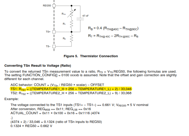
    I cannot find a 7.3.1.5.2 in the datasheet, as there is no numbering. However, I am assuming what you're referring to is on page 16:

    EDIT: That RTs1 represents the ratio of the voltage at ts1 to REG50; I understand this now. So the next step is to use a potential divider equation, to get the value of the thermistor resistance, then use this to get the temperature. Correct?

    Regards

  • Hello Roger,

    I tried the above algorithm, and these are the results:

    The program stores the ADC value for temperature in the variable bq_pack.bq_devs[0].temperature1. So the I am using the following code to calculate the temperature:

        float v_ts = (((bq_pack.bq_devs[0].temperature1) + 2.0) / 33046.0) * 5.0;                       //calculate voltage across TS1- and TS1+ inputs
        float res_ts = ((9.1 / v_ts) - 3.29);                                                           //calculate equivalent thermistor resistance
        float temp_ts = ((4250.0 * 298.15)/((298.15*(log(res_ts/10.0) / log(2.718))) + 4250.0)) - 273.15;       //calculate temperature in celsius
    

    For line 1, that equation is sourced from the datasheet (see my last post).

    For line 2, the thermistor is in series with 1.82k and 1.47k resistors, and I am using a potential divider equation to find the equivalent resistance of the thermistor.

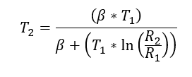
    For line 3, I am calculating temperature using the equation:

    T2 is the desired temperature, in Kelvin, and R2 is the equivalent resistance calculated in line 2. T1 is 298.15 Kelvin (25 deg. Celsius) and R1 is the thermistor resistance at T1, which is 10k.

    Regards

  • Hello Roger,

    I found a solution (somewhat). I decided to use temperature circuit 2, which uses IC 2 on the EVM. The temperature value I am getting is around 37 degrees Celsius, but I 'solved' this issue using an offset of about 13 degrees. Not sure why this happens, as I've verified that my calculations are correct.

    For temperature circuit 2, measuring the voltage across TP1-8 and TP1-7 gives 3.772V. For temperature circuit 1, using IC1, the voltage across TP1-4 and TP1-3 is 0.377V. I think this is the problem.

    I was not sure why this happens, so I decided to test the ICs. These are the voltages I got:

    IC1: 4.372 V

    IC2: 4.778 V

    IC3 : 4.772 V

    I believe the lower voltage of IC1 may be the issue. Can you clarify this?

    Regards

  • Here is how to convert Temperature registers 0x0F and 0x10 to temperature.

    1. Calculate RB and RT.
    Page 19 figure 14 have two equations.
    RB = .4 (RTH@40C – RTH@90C) , .4(5826-1260) = 1826.4
    RT = Rth @40C – 2Rth@90C – RB
    I got RB=1826.4 and RT=1479.6.


    2. Calculate TSn Ratio.
    Page 19 has more details and example but use below equation. I took it out from the datasheet.
    TS1: RTS1 = ((TEMPERATURE1_H × 256 + TEMPERATURE1_L) + 2) / 33,046
    TS2: RTS2 = ((TEMPERATURE2_H × 256 + TEMPERATURE2_L) + 9) / 33,068

    Using same example in the datasheet.
    Reg 0X0F == 0x11 and Reg 0x10.= 0x16 (TS1+ and TS-).
    Actual count of 0x1116 is 4374.
    Ratio is= .1324

    3. Calculate Rth (temp)  = (RB /Ratio) - (RB + Rt)
      =(1826.4/.1324)-(1826.4+1479.6)
    10488


    4. Using ideal value Rnom in the excel look up chart.
    It is between 20C and 25C. Find the slope.
    Temp= 23.84C.


    Below table is from thermistor we used.

    Rnom Temp
    501.1 125
    567.8 120
    644.8 115
    733.8 110
    837 105
    957 100
    1097 95
    1260 90
    1451 85
    1670 80
    1928 75
    2233 70
    2596 65
    3027 60
    3543 55
    4164 50
    4914 45
    5826 40
    6941 35
    8309 30
    10000 25
    12100 20
    14730 15
    18030 10
    22210 5
    27550 0
    34390 -5
    43220 -10
    54720 -15
    69840 -20
    89880 -25
    116690 -30
    152920 -35
    202380 -40
  • Try this and let me know whether it works or not.
  • Hello Roger,

    Using up to step 3, the code does the same thing, and gives a alue in the 30s range, that I must offset.

    Unfortunately, I do not have access to an accurate temperature measuring device to create an excel lookup table as you did in step 4, so I am still using my equation I described previously. Chances are then, that this is why I am getting an error.

    Do you have any information of the measurements I took for the 3 ICs?

    Regards

  • Can you exactly point out where you measure these measurements?

    Please see top right side of evm and get me the evm number.

    These measurements are not typical measurements of PL536A LDOs.

    IC1 measurements looks odd.

    IC1: 4.372 V

    IC2: 4.778 V

    IC3 : 4.772 V

  • The IC measurements are taken across TP-VPROG1 and TP-VSS for each IC.

    The EVM number is: bq76PL536EVM-3 HPA507A 4055500097.

    Regards
  • IC1 is definitely bad. I don't think you will get good measurement from IC1.

    IC2 and IC3 are low side as well. They should be close to 5V. They may be okay but I won't be surprised if measurements are off.
    IC1 is bad for sure.
  • Are the voltages an indication of the voltage of the cells connected to them? Because when the EVM was first connected to the cells, 4.77V was the voltage measured across all ICs.

    Regards
  • 4.77V is low side of LDOD. The typical is 5.0V.

    But your IC1 is definitely bad. 4.372 is not good.

    I suggest you to replace the IC.

  • Thank you for the reply and advice, Roger.

    Is the IC removal as simple as applying heat to the IC, letting it slide off, then placing the new IC in that spot and apply heat to re-solder?

    If I continue using the EVM as is, would any of the other ICs become damaged?

    Regards
  • It will not damage other ICs.

    If you can communicate to 3 ICs then you should keep using it as it is.

    But, just remember that measurement may not be accurate.

    So, are you able to communicate to all three devices?

    Remember, each ic has own local gnd so pay attention to how you apply and make measurements.

  • Hello Roger,

    I was able to still communicate with all three devices. I performed some balancing on the 15 cells connected to the EVM, and everything went well.

    However, I started getting some erratic readings from the EVM when using the Aardvark adapter. I disconnected the adapter and tested all 3 ICs again. These are the results now:

    IC1: 4.276 V
    IC2 : 2.003 V
    IC3: 4.776 V

    I understand this means that IC2 is dead; in fact, the balancing resistors for P1 and P2 for IC2 are locked in the 'ON' position. I can only use IC1 now.

    What I am trying to understand now is why this happened.

    Regards
  • IC2 is not good. It means that you won't be able to communicate to IC3.
    I don't know what you are doing but ICs are damaging.

    Have you check the pl455A evm user's guide?
    I think I mentioned before. Each IC has own local gnd so you need to be careful how you power up and do the measurements.


    I think you might be talking about the resistor divider which is for power supplies.
    They won't damage the IC.

    Check the user's guide 1st and show me how you power up the ICs.
  • Hello Roger,

    I am using the bq76PL536EVM-3; not the bq76PL455.

    I demonstrated my design before, in this thread: e2e.ti.com/.../573467

    Regards
  • Yes, meant to say pl536A user's guide.
    Can you show me how you power up the IC?
  • Hello Roger,

    When you say power-up the IC, do you mean how I connect the cells to the EVM?

    If so, the tap off points are already connected to the screw adapters for each IC on the EVM. I plug in these screw connectors to the corresponding EVM ports to power the device.

    Regards
  • Hello Roger,

    Just checking to see if you have any updates.

    Regards
  • www.ti.com/.../sluu437d.pdf

    Above is the user's guide. You can find the proper way to connect the cells.

    Do you think you can take a picture and post your set-up?

    I have been using same evm for past year or so.
    I can't tell you how IC got damaged. I need details on things you tried on EVMs.
    No matter what, you have to replace the IC2 for you to communicate to IC3.
    I personally recommend users to use P/S for as shown in the user's guide. Limit your P/S current to 20 to 30mA.

    Just remember that each IC has own gnd so you need to be care when handle the EVM.


    Get a new IC and replace 2nd IC.
    Until then you are limited to bottom IC.
  • Hello Roger,

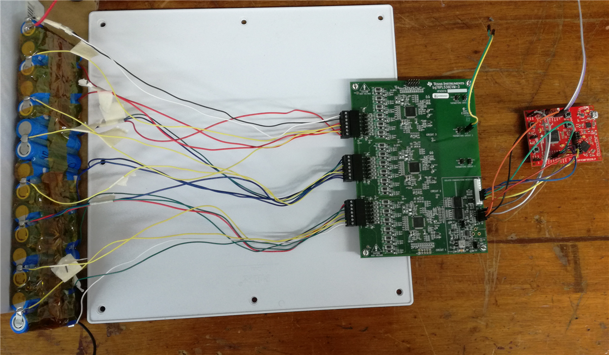
    Yes, I have following the instructions in the document. Here is my setup:

    Regards

  • little hard to trace the wires from cells to evm.
    Do me quick measurements.

    check the voltage between TP2 and TP3 on evm.
    Also between TP4 to TP5...

    Are you doing charging and discharging as well?
  • At the moment, I am not charging nor discharging, but I have discharged the battery before, while connected to the EVM, using the battery terminals. These are the two wires on the ends of the battery: black for negative, red for positive.

    I took the measurements, and these are the results:

    Between TP2 and TP3 : 1.92 mV
    Between TP4 and TP5: 0.00 mV

    Regards
  • I assume that all input cell voltages are okay, right? just make sure every wires are connected properly. measure every cell voltage and make sure they are okay.
    If wires are connected properly then I really can't not tell you what happened. I remember, IC2 was okay in the beginning.
    Your set-up looks okay.,, IC2 won't get damage connecting MSP430 to the evm, or communicating the device. Only way is wrong wires connection, shorting circuits on IC2 with something on IC1 and IC3... Otherwise, they are pretty robust.


    Your next step is to replace 2nd IC.
    you are okay to keep using it as 1S evm for now.
  • Yes, all cell voltages are within the range 3.2 - 3.3 volts, which is the nominal voltage for LiFePO4 cells. And I did re-check all the leads going into the connectors for the EVM, and everything is fine.

    I really do not know why the IC is bad either, as I have made no bad connections; when everything was working well, the IC voltages were around 4.8V, then suddenly IC1 dropped to 4.3V, then IC2 dropped to 2V.

    The next step, indeed, is to change IC2 and hope that this is not an underlying problem. If it were, what other components can cause this to happen?

    Nevertheless, thanks for all the help.

    Regards
  • I wish I really have answer for you.
    it's probably not the component causing the IC to damage.
    Random cell connect is possibility but then PL536A support random cell connect.

    This is what I recommend.

    1. Replace the IC. YOu have no choice.
    2. Connect cell from bottom IC. Connect cells to IC 1 then IC2 and IC3... This is best way to connect cells to PL536A.
  • Sure thing, I am going to replace IC2. In that regard, a bq76PL536A IC is the replacement IC I ordered; would it have made a difference if I went for a bq76PL536A-Q1 instead?

    And when I'm connecting, I do start at IC1 then IC2 then IC3. Is there an order for disconnecting as well, because the order I disconnect in is IC3 then IC2 then IC1.

    Regards
  • Yes, your sequence is correct for connecting and disconnecting.

    bq76PL536A-Q1 is automotive version. You will have better accuracy but it won't make any diff when it comes to your problem.

    Get PL536A-Q1 only if you need better performance.