This thread has been locked.

If you have a related question, please click the "Ask a related question" button in the top right corner. The newly created question will be automatically linked to this question.

BQ24380: Output Latching in non-fault conditions

Part Number: BQ24380

I have a design in which I am using the BQ24380 as an overvoltage/overcurrent protection monitor for my USB 5V input.  The device seems to work without issue in most cases.  However, I have had a high percentage (15% out of a sample size of 20 boards) in which the IC is not functioning properly.  The error condition is as follows (please also see the attached circuit that is being used):

1.  Vin is at a valid non-fault voltage.  It being USB, Vin = 5V.

2.  Vbat is pulled to ground through a 100K ohm resistor so that an overvoltage fault condition never exists.

3.  Chip Enable is active.

When I first connect 5V, the output goes high without error.  In this case, the BQ24380 is working properly.  The error condition occurs after I remove the input voltage and then connect it again prior to allowing the input and output voltages to discharge all the way to 0V.  If I reconnect the 5V without allowing the input and output voltages to discharge all the way to 0V, the output latches at about 100mV and the FAULT signal is pulled low.

At the moment, I'm not sure why this is occurring.  It seems as though I am using the part within spec.  I am looking for any information on what scenarios might lead to these results.  I have verified that there is no actual fault condition (overvoltage, overcurrent) so I'm wondering what may have damaged this part so that it thinks there is one.

  • I forgot to add the circuit diagram....

  • Hi Casey,

    Do you think you can get us a scope capture at TP331?
    Capture OUT and Fault as well if you can do it.

    Thanks
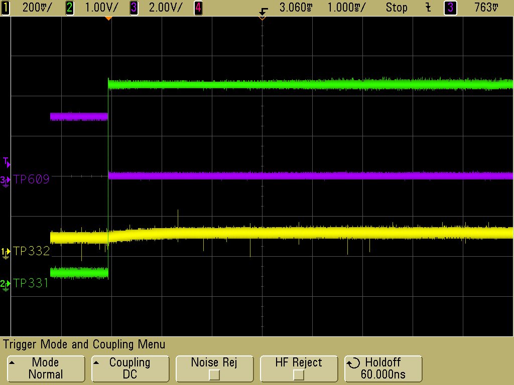
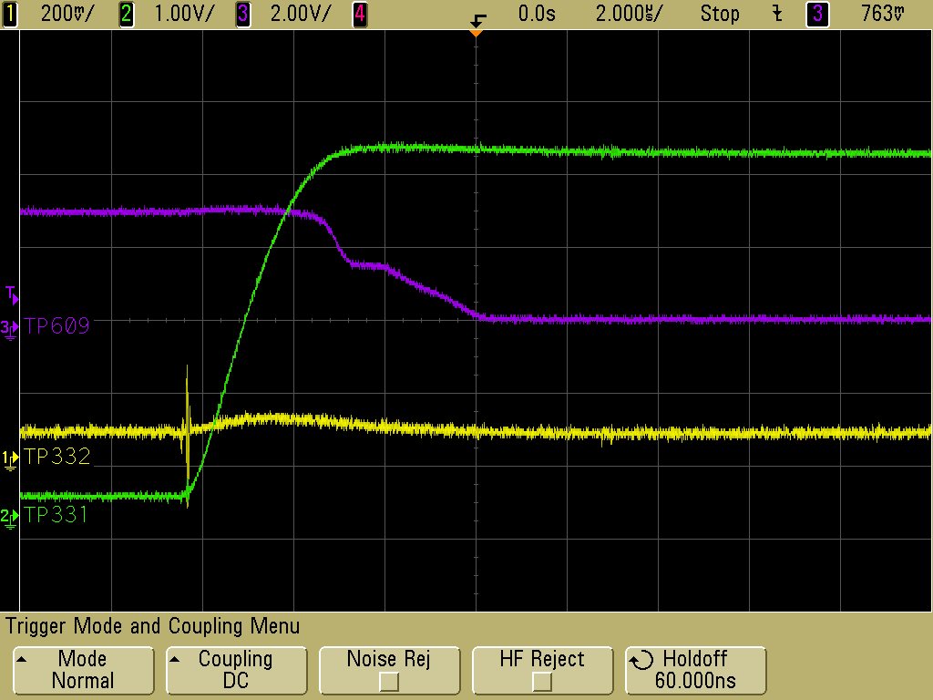
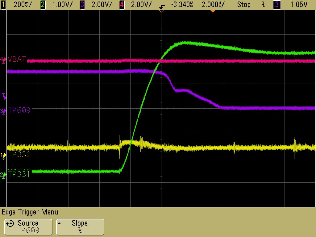
  • The attached screen shots show the input, output, and fault signals.  They are a zoomed out and zoomed in version of the same fault event.

  • thanks for your plots.

    Can you do me few more things.
    1. Schematic shows that you have /CE connect to GND. Just double check /CE pin is not floating. I think it does but just to check. It will prevent the start up again.
    2. Can you double check your 3.3V pull-up voltage is still there? I noticed that /Fault pin takes 4-5uS from high to low. Check you3 3,3V.
    3. Take a page 9 of datasheet. You will see Vo and short circuit will disable the FET. I think we can eliminate Vo but we still need to check out the short circuit current. DO you think you can measure the short circuit.

    Your plots are really helpful....
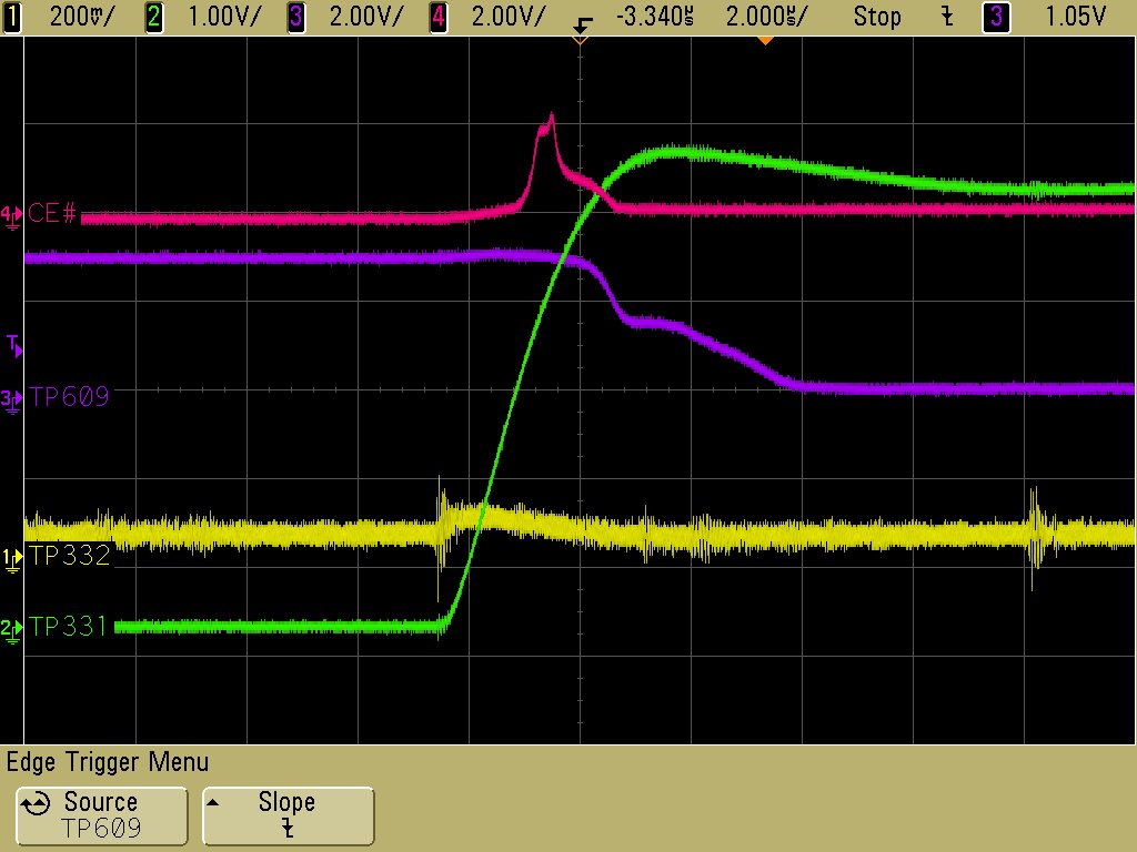
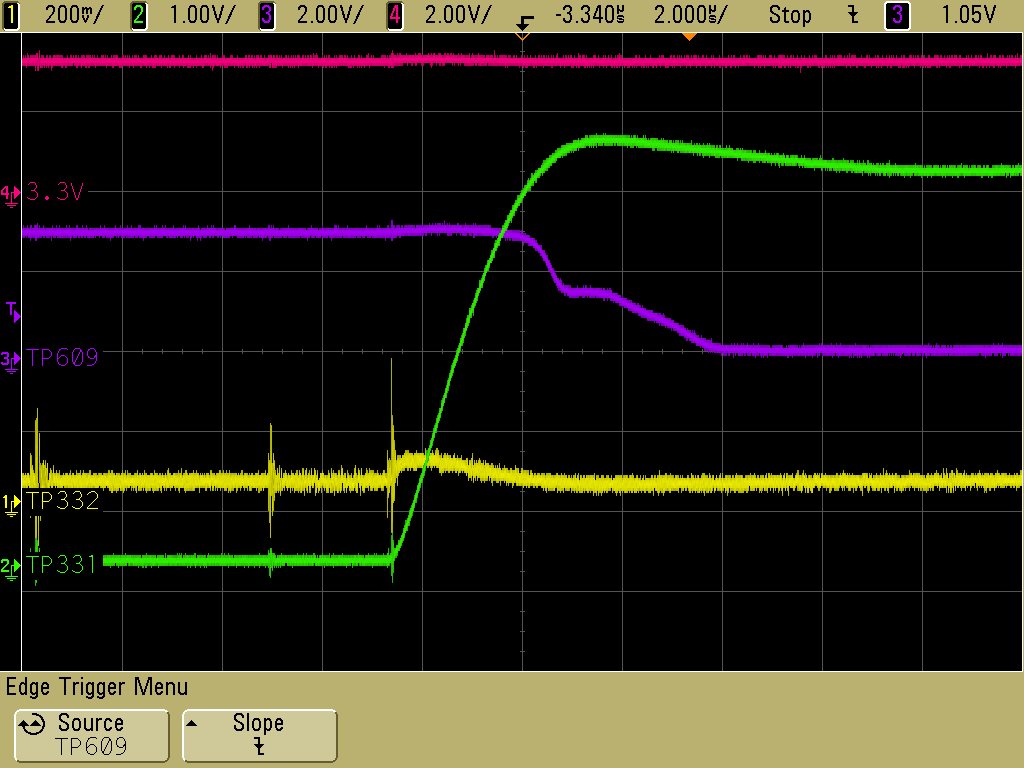
  • I have attached a few additional plots below.  The first shows the Chip Enable signal during a fault event, the second shows 3.3V during a fault event, and the third (in the spirit of ruling fault scenarios out) shows VBAT during a fault condition.  

    Measuring the instantaneous current through the device could prove to be difficult.  I do have a differential probe and I could probably replace the inductor on the input side of the BQ24380 with a small sense resistor to allow for measuring the voltage across the resistor.  However, I'm not sure that is necessary.  The overcurrent threshold on the BQ24380 is 1.5A.  I am using a USB port on my PC to power the input to the BQ24380.  A typical USB port will only allow 500 mA.  If the BQ24380 was pulling 1.5A, I am sure that I would see some disturbance during the overcurrent event on the input supply.  However, in none of the screen shots I have provided will you see any indication of a high current event on the input supply.  That said, I will provide you with some additional information that is pretty interesting.  Instead of just applying 5V to the input, I ran a test to ramp up the voltage slowly with a bench top supply.  In this test, the output would work every time.  I then would ramp up the input voltage so that it exceeded the overvoltage limit and the fault tripped at the appropriate voltage.  However, when bringing the voltage back down below the overvoltage limit (minus the hysteresis), the fault stayed active.  It wasn't until I removed the input voltage and allowed it to decay that I could then reapply the input voltage and have it work properly.

    One thought I had is that the ramp up was proving that the BQ24380 is having trouble with the initial in-rush currents of charging the 1 uF capacitor.  However, the part is designed to be able to handle that.  There are several examples in the datasheet to display the behavior of in-rush limiting and my screen shots don't look similar.  That said, it is interesting that the fault never went away in my above test after the initial overvoltage.  Could there be something internally wrong with the fault circuitry?  Perhaps the first fault that I am seeing is due to in-rush and, because the fault circuitry isn't working, the output never turns back on.

    There is also an overtemperature fault condition.  However, I'm not sure what would cause that to trip given that the current is low.

  • Hi Casey,

    One quick question for you.
    Does it recover?
    Device should try to recover.
  • No, it does not recover. It does not even appear to try to recover. This is why I thought the overvoltage test that I ran was interesting. This gave me a benchmark test in which I know what the fault is (overvoltage) and when I remove the fault condition, the part does not recover. Only after removing the input voltage and allowing the part to power down does it recover. As you mention, it is supposed to recover as soon as the fault condition is removed.
  • Hi Casey,

    Do you think you can send me one board to me?
    If yes then I can send you the address.

    thanks
  • I could.  But I would want to get the board returned.  This circuit is on a fairly complex assembly.  The rest of the board is working properly and I would like to use this board eventually.  We have a limited number of assemblies.

    Would you be able to return the board?

  • Casey,

    How many boards are behaving like this?
  • I have had three boards behave like this out of a batch of 20.
  • Okay,

    I don't think I want the board then. I may have to debug your board and it may not be useable afterward.
    It could be bad IC or board.

    What is your plan?
    Do you think you can replace with another IC?
    If it doesn't work then we need to focus on your board.
    If it works then we have a bad IC.

    We don't see a problem here with our board.

    What do you think?
    Can you replace with another IC and we can discuss after the result?
  • I can certainly replace the IC and verify that it works after replacing.  I will do this and save the IC that was originally on the board in the case that you may want it for further analysis.

    Thank you.

  • Okay,

    Let me know how it goes and we can discuss after.

  • I replaced the part and the new part is working properly.  We have two additional units coming back from the field with the same failure.  Is there any analysis that TI can do on the damaged parts to hint at what may be happening?  None of the information we have points to an event in which a failure like this should occur.  I'm wondering if perhaps these are being damage due to an ESD event.

  • ESD is a possibility. Let me check with our quality team and get back to you.
  • Can you provide top marketing?
  • I believe you mean "top marking".....if so, it reads "CFE". If you actually mean "top marketing", then I don't know what you are looking for.
  • Hi Casey,

    I am forwarding responds from our CQE.
    *********************************************
    Hi Casey,

    I am the customer quality person responsible for the BQ24380. This device wasn’t familiar to me, you are correct in that the top marking for all the devices will show a CFE. What is important are the “ticks” above and below. This device uses the US:DoD binary year/month convention for top bottom above and below the CFE. There should be come combination of 0 to 4 of these above and below.

    I have checked the device history of the BQ24380 and have found only one return in 2013 from any customer of record which turned out to be a single EOS type case. This tells me there is unlikely to be a systematic issue on the device.

    As a EOS/ESD type event is suspected a FA of this event may not provide much insight in to how to directly prevent the situation, other than identifying the affected pins. For the moment, when this situation occurs TI proposes to check the lot history for any evidence of a wafer or A/T excursion that may have impacted the device in this timeframe. Assuming that none have we would propose to triage this case assuming the issue doesn’t persist into a different lot/batch of units.
  • Ok. There is one dash above the "F" and two dashes below the "F".
  • Hi Casey,


    We looked into the lot history and were able to locate the lot based on the information you provided. The lot proceeded without issues and has not yielded any returns in the 3 years since shipment.


    In this situation, I would consider contacting a failure analysis lab that may assist you in further debugging your issue. One such lab which TI uses on occasion is Chip Targets LLC http://chiptargets.com/ there may be others in your area with similar background.


    If the situation is still unable to be resolved feel free to contact us for more help.