This thread has been locked.

If you have a related question, please click the "Ask a related question" button in the top right corner. The newly created question will be automatically linked to this question.

BQ77PL900: BQ77PL900 Recovery process in Host control mode and Standalone Mode??

Part Number: BQ77PL900

Hi,

I'm using Bq77pl900 IC for checking the voltages of total pack and individual batteries.My questions are 

1)If i want to measure the voltages i have to go into host control mode and measure the voltages through I2C and come to the standalone mode because it has fixed algorithm for maintaining OV,UV,SC protection, so when i'm measuring the voltages in host mode if something is happen like uv/ov/sc to batteries,if i come to standalone mode it recovers ??

2)I want to measure only total voltage is it possible in standalone mode??

3)In host control mode is there any problem comes it protects with in built algorithm??

please help ma ASAP.

Regards,

Prudhvi

  • Hi Prudhvi,
    1. If I understand correctly yes, the recovery depends on the mode selected. If you change modes the new mode controls recovery.
    2. No, measurements are only available in host mode.
    3. Yes, built in protection limits activate in host control mode if enabled, see the bq77PL900 data sheet figure 4. However note that UVFET_DIS should not be set if automatic protection is desired and temperature protection will need to be turned on by the host (typically periodically to reduce average current load) for temperature protection.
  • Thanks for Reply,

    In Undervoltage register i have set UV to 2.9V , when the voltages decreased to UV thresholds then UV protection is not happening.But for OV until it reached to 4.15V cell balancing is happening.How to protect the cells from UV while discharging.Please help me ASAP.

    Regards,

    Prudhvi

  • Hi Prudhvi,
    The protection thresholds in the part operate from the EEPROM values. If the registers are written but the EEPROM write sequence and conditions are not performed, the protection thresholds will remain at the default of 1.4V UV and 4.15V OV. You do not mention the mode used which also can affect the behavior. If you are observing cell balancing above 4.15V, the CBEN EEPROM bit must have been written and you are in standalone mode. The EEPROM is written completely on each write, so if all registers are not set to the proper value, they may be changed. The present EEPROM values may be read back to confirm they match the value intended. The EEPROM should only be written 3 times for long term data storage.
    If you are in host mode and have set the UVFET_DIS bit (such as EEPROM register 7 01001111b) the part will not turn off the DSG below the UV threshold, it is left to the host.
    Check that the FET still works, and check your register settings.
  • Thanks,
    I'm switching b/w host mode and standalone mode, when i'm in host control mode i'm reading the voltages and switch backs to standalone mode.For cell balancing CBEN bit enabled by eeprom write sequence and i verified the register that has written successfully and read the value i have written .But when i write UV register to 2.9V of value 0x0f it also write properly but voltages are dropping below the 3V but UV protection is not happening.Please help me ASAP.
    Regards,
    Prudhvi
  • Hi Prudhvi,
    The part will protect for UV when a cell input is below the UV threshold including its tolerance for the delay time.
    If it is not protecting as expected you must determine why.
    Confirm the discharge FET switches as expected.
    Find the voltage where the system protects.
    Check the register values and cell voltages (with a meter) at the point it should protect but does not, and when it does protect. Compare these.
    If you are using the MCU derived voltage to determine the cell voltage, check its calibration against a meter measurement for each cell in the range of protection. Before checking all cells you might check the bottom cell and top cell over voltage to see if they match a meter value. If there is an offset error the system may be over OV and also over UV when expected. With a scale error the reported voltage could be correct at one level and incorrect at another.
  • Thanks for reply,

    I have written in eeprom of value 0x0f(2.9V) in UV_CFG(0x07) register successfully.Now i drived with load the the cell discharge balancing is also happening properly,when the cells are normal condition then the status register is 0xC0 and my issue  is when the voltage of one cell reached the 3V then the status register reads that 0x88 properly it means that UV detected and DSG bit goes OFF and CHG bit enable.to discharge the batteries i kept motors load when the UV detected then the motors has to stop because one of the voltage is in UV,but it is still running my motors and voltage is dropping continuously below the 3V like 2.5,2.2,2.0,1.8...

    this is my log

    Status Register :0x88

    3.59   3.52   3.57   3.57  1.64  3.10  3.57  3.63
    3.53   3.52   3.57   3.57  1.57  3.06  3.55  3.58
    3.58   3.56   3 .57  3.56  1.50  3.05  3.57  3.61

    I checked with multimeter FETs of DSG still ON and the voltages are there.How could i solve this problem the entire board will go into shutdown mode and no voltage at load?? how this undervoltage DSG and CHG will work?? Please help ASAP.

    Regards,

    Prudhvi 

  • Hi Prudhvi,
    From the status it sounds like the detection circuit of the part is functioning properly. Now you must determine why the FET does not switch.
    Check that the DSG pin is not damaged and the voltage is ~ 12V below BAT pin when normal (on) and the voltage switches high when UV (off). When off it should match the BAT pin which should be at the FET's source voltage level. With no voltage between gate and source the FET must be off and current will/should not flow through the FET.
    Be sure the DSG pin is connected (through appropriate components) to the discharge FET gate.
    Be sure the discharge FET is not shorted from damage and there is not a short across the discharge FET on the board.
    Be sure the FET footprint used for the board is correct so that drain and source are not reversed.
    Be sure the FET installed is a P-channel type.
  • Thanks for reply,

    I changed the default thresholds in eeprom more than 3 times does this effects the IC discharge and charge functionality???

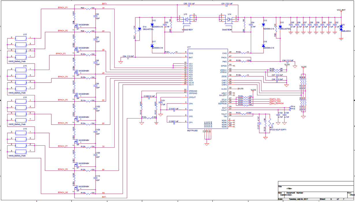
    I will share my bq77pl900 custom schematic please verify and let me know if any mistake done??

    in the schematic i'm mounting two diodes(D14,D15) reverse direction then only the circuit turns ON please check this also.

    Regards,

    Prudhvi

  • Hi Prudhvi,
    Your schematic looks rather normal. The 10k R97 should slow discharge of C94 to keep the part alive during short circuit timing. D14 provides the supply current for the part and prevents BAT from falling too far below the FET source since the BAT pin is also the reference for the FET source voltage.
    If you have reversed D14 and D15 the part's supply current will create a large voltage drop across R97 (and R98) and the driver will have an incorrect reference for the FET source. The DSG and gate voltage will then be low with respect to the FET's source and the FET will likely be on whether the PL900 is trying to turn the FET on or off. D12 and D17 may actually be providing supply current to the PL900 through the DSG pin.
    Install D14 (and D15) correctly and see if the FET switches properly.
  • If we write in eeprom more than 3 times is this effects the IC charge and discharge functionality.
    Regards,
    Prudhvi
  • Hi Prudhvi,
    Sorry I skipped the write question.
    The maximum number of EEPROM writes is recommended as 3 in the "Recommended Operating Conditions". More writes are not expected to change the charge and discharge switching functionality. The concern is for the long term EEPROM data retention. If the EEPROM degraded over time from excessive writes a PFALT error may be generated. FALT will turn off CHG and DSG as described on page 38 of the bq77PL900 data sheet.
    If you have written a part many times during development you may want to replace the part before placing it in long-term service.
  • Thanks for your support,

    I'm very thankful to you for giving support,problem solved actually the current sense Resistor has to keep 0.001(very Important).

    Now the UV and OV is working properly.

    Regards,

    Prudhvi