This thread has been locked.

If you have a related question, please click the "Ask a related question" button in the top right corner. The newly created question will be automatically linked to this question.

BQ76PL455EVM: Issue regarding GUI

Part Number: BQ76PL455EVM

Hi All,

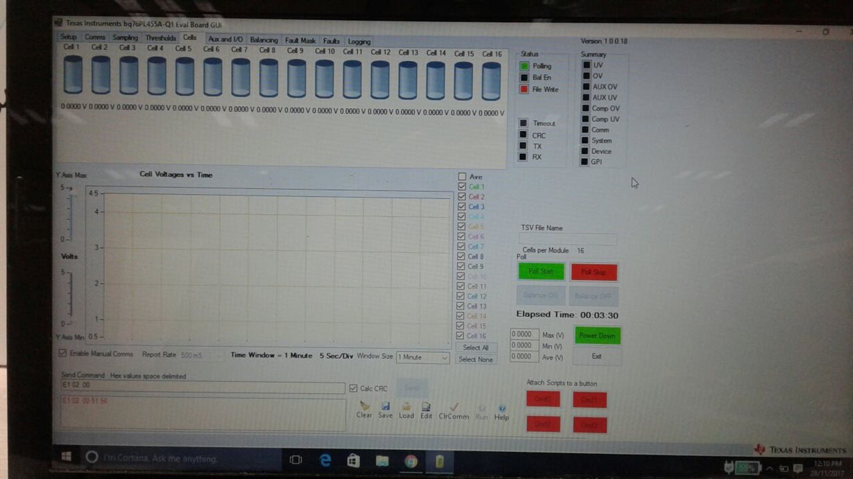
I am facing an issue communicating with BQ76PL455EVM using the manual command section. I am using a single evm board to monitor the voltages of 16 cells. I want to use the manual command feature to communicate with the board but I am unable to do so. When I enable manual command section I do not get the packets logged window which is seen in the datasheet of evm. Hence, I can only send commands(seen in red) but never receive a response from the GUI (which is seen in blue). I am able to poll the cell voltages using the Poll start button in GUI. My question is whether this is an issue of GUI version or an issue of the EVM. As the EVM is not responding to manual commands from the GUI, I have a doubt that it may not respond when I use a micro controller to interface the chip.

Any help would be appreciated.

Regards,

Rohan Parwardhan 

  • Hi Rohan,

    What is the hex value you are sending? This function works fine - i have used it many times.
  • Hi David,

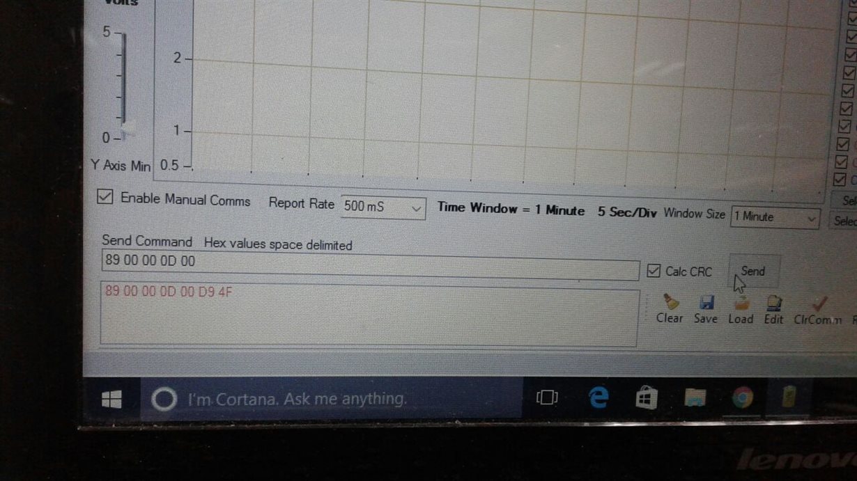
    As of now I have tried the hex command 89 00 00 0D 00 with calc CRC box checked. Please find a few images attached. For the second image please ignore the command. I just wanted to show that packets logged window is not appearing in GUI.

    Regards,

    Rohan

  • Hi  Rohan,

    Try unchecking the "Enable Manual  Comms" button and try again. I never have this checked and my communication works. 

  • Hi David,

    Done that. Tried a comm reset as well as power down and power up the device but no luck. I would like to understand whether this issue may cause an interference when I use STM32 microcontroller. Would like your help regarding this issue.

    Regards,
    Rohan
  • Hi Rohan,

    Just to make sure... the GUI can poll cell voltages using the button, correct?

    Have you put a logic analyzer on the UART pins to see the traffic?

    There should be no issue communicating with a micro as long as the UART baud rate's match up.
  • Hi David,
    Yes I can poll cell voltages using GUI button. I am using Hercules software to check for UART but getting no response. I shall try communicating once more and keep u posted. Thanks for your support.

    Regards,
    Rohan
  • Hi David,
    I tried mannual commands once again. When I gave a command to change no of channels in command channel register(addr 3-6), the register value was updated. However when I sent a command to read values, I did not get a response. Is this something I must be worried about?

    Regards,
    Rohan
  • Hi Rohan,

    Can you confirm the hex command you are trying to send? I would also look at the data being sent to make sure that it is actually making it to the part.

    If the GUI can poll the cell voltages, it should be fine. It is doing the same thing an MCU would do
  • Hi David,

    We tried to power down the IC using manual command. When powered down, we know LED D22 will turn off so can serve as an indication. At first we wrote hex value 40 in register 12(device control) using show registers tab. The device powered down. Next we tried to send a manual command to the chip. Command sent was 81 00 12 40 with calc CRC enabled. The device did not power down. When we read the registers, device control was at 00 and not 40.

    Would like clarifications with this issue.

    Regards,
    Rohan
  • Hi Rohan,

    If possible, I think the next step is to look at the data being sent on the TX/RX lines to be sure that it is what we are expecting.

    To be honest, I haven't encountered a situation like this where the GUI works with the button interface, but the manual commands did not work. This will help us focus our debugging on PC vs board. Since the buttons work, the board should be just fine I think.

    If you have a prototype board (such as an Arduino or Launchpad), that would be useful as a somewhat quick check as well.
  • Hi David,

    I figured out the error. I was sending the wrong hex code in manual command window (12 should have been 0C). Now i am able to write values to registers using manual command but unable to read.

    Hence I put up a scope on rx and tx. I am able to receive a response, just that it is not being shown on GUI. This is my guess as to what is happening.

    Moving ahead, i connected a microcontroller to the EVM. I have sent the same command which is for a power down from my microcontroller (hex code is 91 00 0C 40 crc calculated), but the evm does not enter into power down. I checked the waveforms on scope and waveform of microcontroller is exactly as that as generated from evm manual commands.

    I do know that the evm addresses the board as 00. Hence for device address i am putting 00. I would like to know whether i must use auto addressing to find out board address and then send a power down command.

    Regards

    Rohan