This thread has been locked.

If you have a related question, please click the "Ask a related question" button in the top right corner. The newly created question will be automatically linked to this question.

BQ76920: Inaccurate cell voltage readings

Part Number: BQ76920

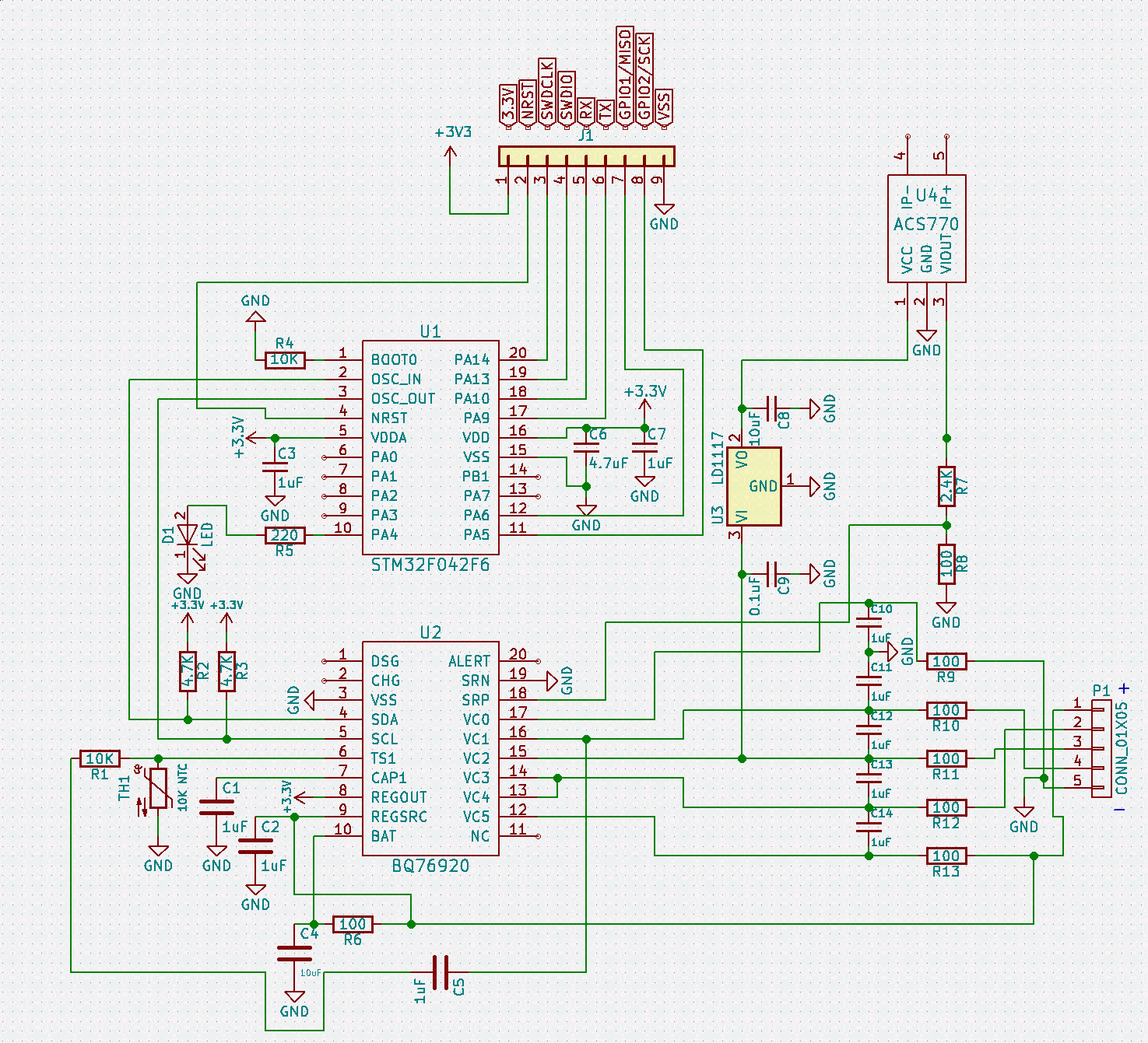
I am trying to implement the BQ76920 in a battery monitoring application. The schematic is below

When reading the individual cell voltages I have found the VC2 is very inaccurate, usually around 3.67V when it should be around 4.14V. 

BQ76920 Cell voltage error
Actual reading (V)        BQ76920 Reading (V)
Cell 1 4.13 4.13
Cell 2 4.14 3.62
Cell 3 4.08 4.67
Cell 4 4.14 4.13
Total 16.4 16.53

As you can see from the above table there is quite a discrepancy between my readings and the actual ones. What could be causing this inaccuracy and how can I rectify it?

Many thanks,

Tom

  • Hi Tom,
    In your schematic regulator U3 loads the VC2 input pulling current through the filter resistor R11. Any regulator current will reduce the voltage of cell 2 and increase that of cell 3. The sum of the reported cell 2 and cell 3 voltage is approximately the same as the sum of your cell voltages. You will need to move the regulator feed to the cell terminal with its own resistor if needed. Typically you would want to draw current from the full cell stack.
    Also the connection of C5 is unusual. From the data sheet a switch might be used in that position for boot, It is not clear what the capacitor might affect operation.
  • Thank you for the reply. Removing the U3 fixes this issue, I will move the trace to before the filter resistor on the next revision on the board. As for C5, I am using this to provide the voltage edge required to turn on the BQ76920. Will any issues be caused due to this?

    Tom
  • Hi Tom,
    While a switch at C5 would be open and would not affect the temperature measurement (voltage on the thermistor), the capacitor will provide a significant time constant and the circuit will affect the measured temperature. A quick time constant approximation would be the 10k and 1uF of 10ms. The real time constant will be affected by the 10k internal resistor, 10k external, the 1uF C5 and the thermistor resistance at the current temperature. For a constant cell voltage the capacitor will adjust to the voltage. If your system is dynamic the cell voltage will be changing and can also affect the apparent temperature. Since your MCU will be determining the temperature and threshold you may be able to qualify and compensate for these effects, but do be aware of them.
  • Hello,
    What would be other methods of supplying the required voltage peak to TS1? It cannot be done with the MCU as this is powered by the BQ, and I would like it to be automated. Also, you said that having a dynamic cell voltage could cause inaccuracy, and my system does have this. What are the other options of getting a stable voltage rail for TS1?
  • Hi Tom,

    You might look at the apnote bq769x0 boot switch alternatives for ideas. Your schematic does not show FETs so it may not be directly compatible.  You will need some sort of signal and/or comparator circuit.  You need to cause an edge on TS1 for boot then not load the circuit to corrupt the temperature reading.