This thread has been locked.

If you have a related question, please click the "Ask a related question" button in the top right corner. The newly created question will be automatically linked to this question.

BQ76PL455A-Q1: BQ76PL455A-Q1

Part Number: BQ76PL455A-Q1
Other Parts Discussed in Thread: BQ76PL455EVM

I'm using The BQ76PL455EVM with some BQ76PL455A-Q1 boards manufactured by LG Chem and supplied with their 16 Li cell 30 Ah batteries.  The software is on a Samsung PC running Windows 7.  In a stack of 2 (EVM + LG), all 4 boards are correctly identified and given board addresses,  but two of them throw up errors "Board communications at address 1 can no longer be found. Check communication connections. repower all boards. Close & restart this tool". I've tried this, but there's no change.  If I ignore this and run the auto-address again,  I get different errors like "Comms timeout" or "An error has occurred: Conversion from string &H to type 'Integer'  is not valid" .  It's not clear to me yet whether the error boards are faulty or whether the registers are incorrectly set as I can't access or modify them.  My original diff. comm link was with ribbon cable, 1.5 mm spacing. I replaced it with two twisted wire pairs (COMMX+- and FAULT+-) 150mm long, but still no improvement.

The two other boards work OK and I can poll the cell voltage data and read their registers, so I don't think it's a connection problem.  However, when I  connect them up as a stack of 3 (EVM + LG +LG) I get  "An error has occurred: Conversion from string &H to type 'Integer'  is not valid" or e.g. "CRC error 45CA received, 9445 expected" and can't read the registers or poll for cell voltages.

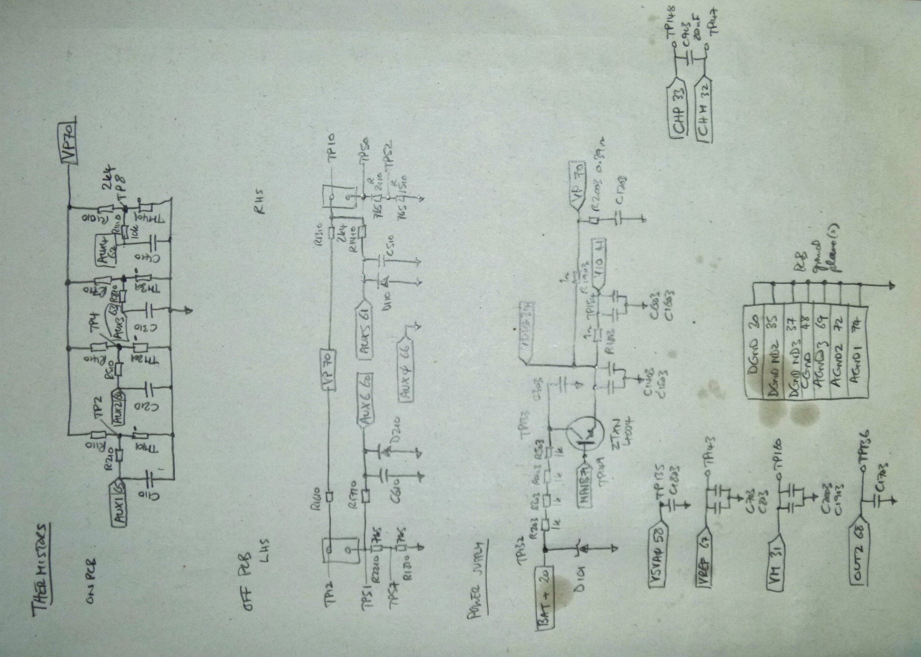
I discovered that the LG boards aren't wired quite as recommended in the data sheet:  VIO is not connected to VP (through 1 ohm resistor) and RX is tied to VIO through a 100k resistor;  the WAKEUP pin goes to ground through 100k. I have modified them as recommended, but there's no improvement.

Any help you can give would be much appreciated.

NH

  • using the TI EVMS, the 455A-Q commands 2 differential comm links to transmit signals between ICs in STACK configuration( not uses the UART). The base device thus translates the differential signal to single-ended. Having said, that communication with the 455A-Q1 from the HOST is commanded using the UART( single-ended) communication protocol. Detailed information is available in SLUSC51C document for reference.
    So on the EVM, follow the silk screen ledger:- have the SWTICH flipped to "SINGLE " on the BASE device and on the STACK devices flip it to " DIFF" when using the GUI.
  • Thanks for your reply, Vish, but I do understand all this.    The host laptop is connected to the EVM board via the UBS/UART connector supplied;  the EVM is switched to "SINGLE", appropriate to bottom of stack position and is powerred from a battery of 16 Lithium cells; the EVM communicates with the additional board(s) via the high-speed differential link.  This all worlks because the 2 boards are given addresses and I can poll the cell voltages and two auxiliary channels on both boards.  I can also read the internal registers. The problem arises with more than 2 boards, when I get comms errors.

    The additional boards aren't TI EVMs, so there's no single/Diff switch. They are made by LG chem and seem to be pre-programmed to operated in diff comm mode.


  • Hi Nick,

    It's little bit hard to debug your issues.
    I don't know how device is programmed.

    One option is for you to connect our GUI to the LGC board.

    DO you have their schematic we can review?
    How is VIO connected? Base and Stack are diff.
    If you have our GUI then you can try to communicate it.

    circuit for base and stack are diff. Please check the datasheet and make sure you are following it.
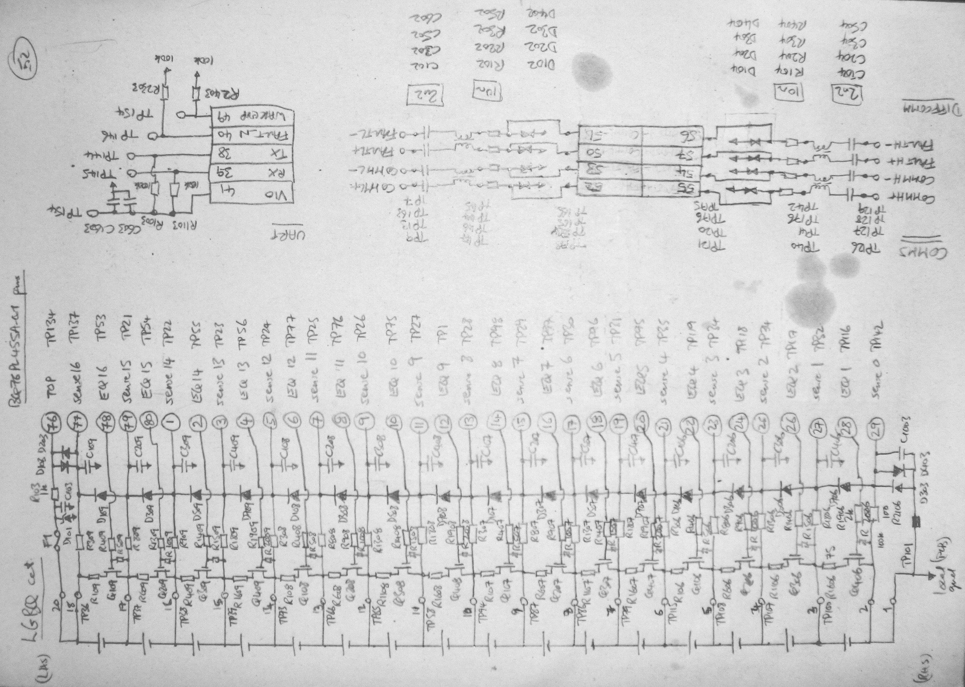
  • Roger, thanks for your reply. I have been able to use your GUI with the LGC board. The problem arises with a stack of two or more (EVM +nLGC) when comms timeouts appear. I have a hand drawn circuit for the board which I will attach on my next message. VIO is connected to VDIG via a 1 ohm resistor with decoupling, as is VP. I have also written a program for PIC18F45K22 following your software guidelines for addressing & configuring. It works with one LGC at 250kbaud via the UART (TX,RX,GND + WAKEUP and FAULT_N pins). It reponds to a request for address with 00 00 0000 as expected. It also responds to sampling and reading 16 cells plus two auxiliary channels: 23 AAAA, BBBB, ........RRRR, CRC but the first two cells' (16 & 15) data is corrupted (e.g. 007C, 83DF) whereas all the others are correct (approx BC00 or 3.68 +/- 0.02 V . I haven't tried it with two or more in a stack yet.
  • the UART config ik OK.
    however, the TVS diodes on COMMH+,CoMML- seemed to be drawn wrong. please check polarity.
  • check the schematics the polarity of the TVS diode on the commH/commL line on the daisy-chain.
  • The two-terminal TVS diodes measure approx 0.9 volts in the forward direction, 0.57 reverse biased, using a Fluke Scopemeter 123 on the Diode range. This is without any power applied to the board.  When I connect the board (battery connectred) as device 1 (EVM= device 0) daisy-chained together, I measure less than +/-1 volt using a 10:1 probe (input capacitance 20 pF).  Is this the source of the problem?  Nonetheless the EVM returns register information and polls cell voltages correctly. It's only with additional boards in the stack that comms cease.

  • appears to be the twisted cables is exceeding the total allowed capacitances when stacked. The COMMH/COMML are not strong to drivers to drive anything greater than 140pF! This constraint is true for the COMML, COMMH or FAULT_N in between the ICs(stacked). Please refer to the SLUSC51C for the equation 8.1.2.2.3.

    Also, try to use scope probe ~ <<< 12pF/10MOhm/200MHz bandwidth probes to checkout the COMMH-COMML debug. and use the MATH function of the scope to look at the [COMMH ( minus) COMML] to see the differential signal.

    hope this helps out.
    vish