This thread has been locked.

If you have a related question, please click the "Ask a related question" button in the top right corner. The newly created question will be automatically linked to this question.

BQ76PL455A: 67 PIN test find bigger ERR

Part Number: BQ76PL455A

Dears,

We use 6PCS bq76pl455a series connection in one battery PACK,for EV BMS application.

We find through the MCU,each pcs BQ76PL455A have different cell voltage output,so we test REF value at 67 PINS,the test value is 2.496~2.5V,the test value is bigger than datasheet said as below:

so we can not get a normal Vref as cell sampling.

Pls help to give us some suggestion how to fix this REF value ?thanks!

  • Hi User,

    Please make sure you are using a four layer PCB, following our EVM (TIDA-00817) layout as a reference, and the recommended decoupling cap scheme is being followed.
  • Dears,

    Yes,we use four layers PCB,the decoupling cap is followed the recommend from datasheet,we will study the TIDA-00817 deeply.

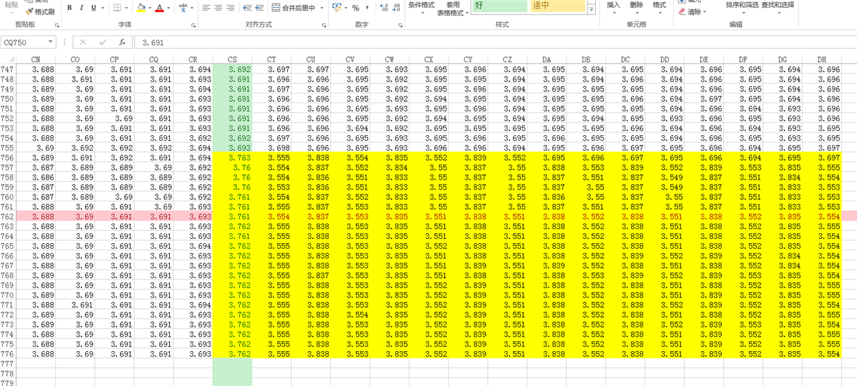
    We test the BMS board and find the log file as below: the yellow mark data is read from one of the six BQ76PL455A(it is nearest the MCU ),we can see the sampling cell voltage is abnormal,if restart to power on,it will be OK,what can make this abnormal?we need some suggest.

  • Hi User,

    Here are a few additional suggestions that are likely to further alleviate accuracy errors. Having even one of these incorrect can cause accuracy issues, and a combination can compound the problem over time (similar to what you are seeing on startup), so please make sure these are done with the utmost care:

    - Ensure settling time is appropriate for the filter capacitors chosen: please ensure the AFE output settles to within < 1/2 of the ADC LSB for best measurement accuracy.

    - Ensure the Zener diodes chosen have very low leakage current, within the spec described in the datasheet and design recommendations. Otherwise, accuracy will drop significantly, so check the Zeners used for leakage.

    - Ensure the filter resistors chosen are within the recommended specifications, as higher resistance on the sense lines will reduce accuracy.

    - Ensure the ground plane and device grounding used in the design match the datasheet recommendations (short ground traces, no other traces in the GND plane, decoupling capacitors as close as possible to the relevant pin, isolation keepouts, etc).

    If you run into any issues after following these suggestions carefully, let us know so we can assist you further.

    Regards,
    Vince