This thread has been locked.

If you have a related question, please click the "Ask a related question" button in the top right corner. The newly created question will be automatically linked to this question.

BQ76PL455A: Uart communication in relation to WAKEUP signal

Part Number: BQ76PL455A
Other Parts Discussed in Thread: BQ76PL455EVM

We made a design with the BQ76PL455 based on the EVM.

The BQ76PL455 is on the "secondary side" isolated from the "primary side" which contains the connection to another piece of equipment.

We made a design with the BQ76PL455 based on the EVM.

The BQ76PL455 is on the "secondary side" isolated from the "primary side" which contains the connection to another piece of equipment.

At the moment we power the primary side we see the battery monitor waking up. (VIO gets 5.3V).

When we start communicating with via the GUI from the EVM we see 1 byte is transmitted and immediately the battery monitor is shutting down. We now have to send a wakeup pulse again before we can retry. Each retry gives the same result.

When we slightly change the startup: We force wakeup high until the communication is established (window with the number of devices and address appears). The communication seems to be running without problems.

If we press the “send comm. Reset” button on the second tab of the GUI we experience the same problem as at startup. We se the battery monitor powering down.

Can you give us tips where to look at in order to get this fixed? We can keep the wakeup high at all times but then we cannot put the battery monitor into sleep. We would like to be able to put the battery monitor into sleep.

  • Hi Leo,

    Please share your schematic if possible. I have notified our team of this post and one of us will be able to help look into it.
  • If VIO is 5.3V then device is woke up. You don't need todo anything to wake it up. You are ready to go at this point.
  • use this as O-scope captures to debug. First step is to confirm a clean WAKE is happening.

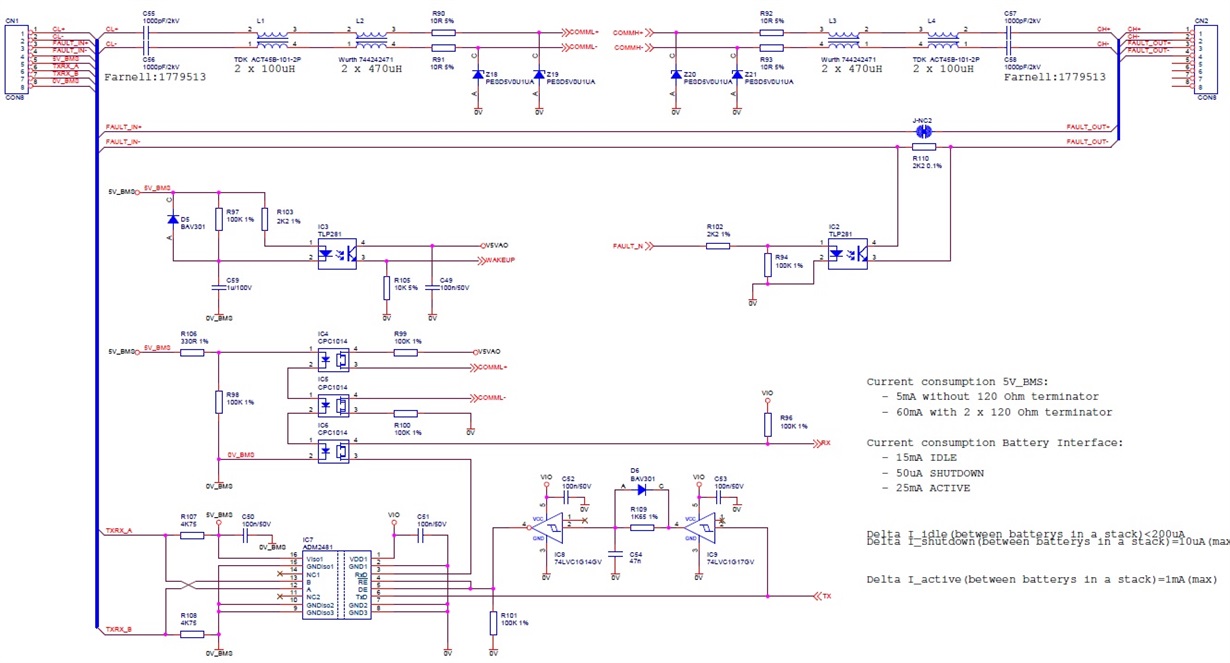
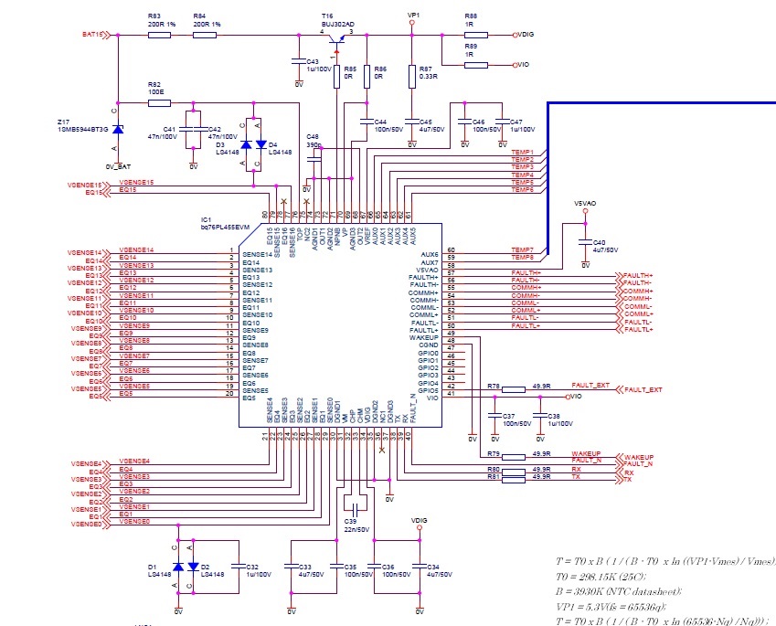
  • Below relevant parts of the schematic.

    We intend to put the battery controller into shutdown during storage and shipment. So we need a way to wake up the battery.

    The problem is in the part that when starting the communication, the battery management IC goes into shutdown (unless we keep the Wakeup input high until it recognized the number of devices present in the TI GUI). After that we can make wakeup low and it keeps working)

  • Hi Leo,

    Sorry my attachment of the scope captures did not come thru the first time.

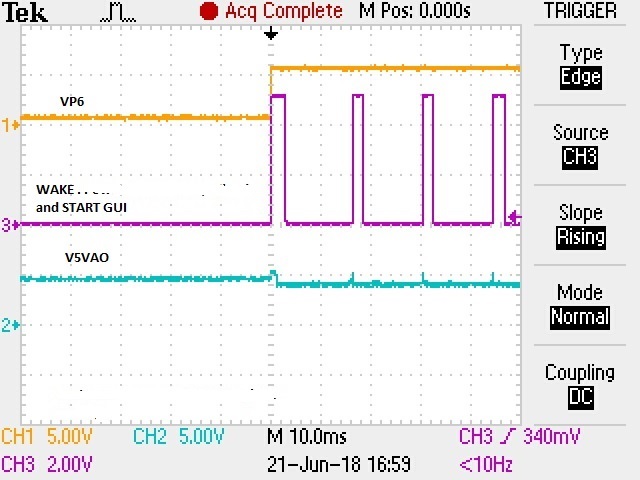
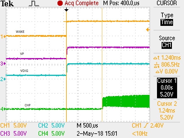
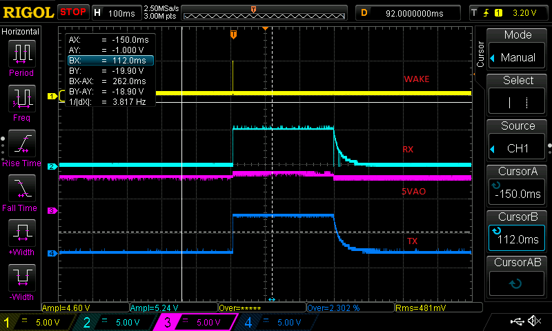
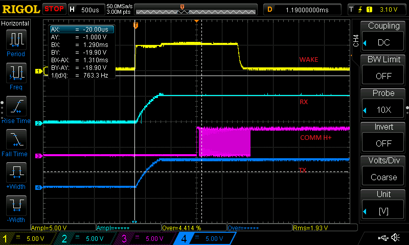
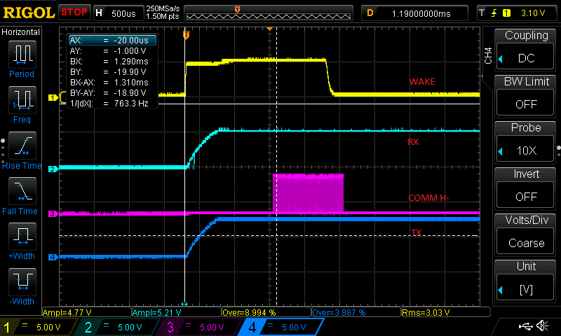
    Sounds like your part is getting wake pulse..below Fig#1confirms, but the device should not shut down..please confirm, if the WAKE pulse is one burst on the base device.  and the v5vAO is up...also on fig #2here is the sequence of the regulators and the

    important Charge function after the WAKE.

    The problem, seems, the device is not receiving a clean wake burst. refer to the d/s exactly pulse width that needed.

    92) What is the STACK voltage?

    FIG #1

    FIG #2

  • Hi Vish,

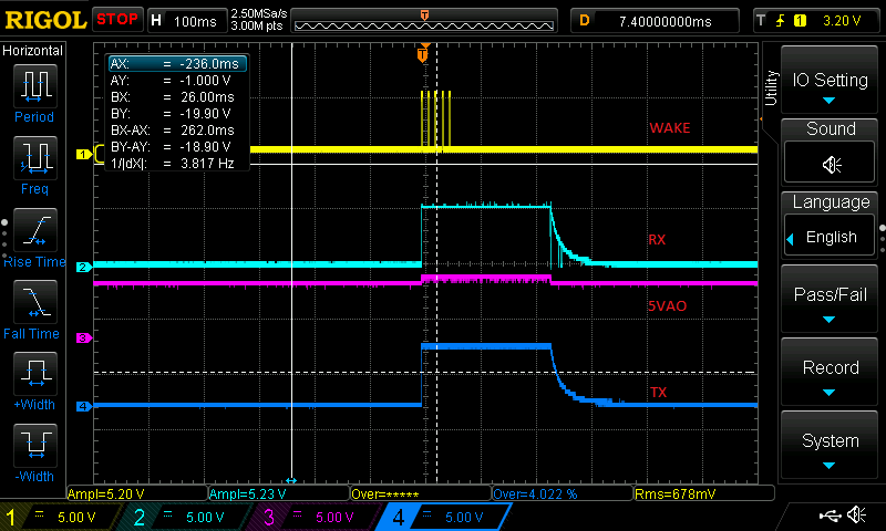
    I have made some scope pictures:

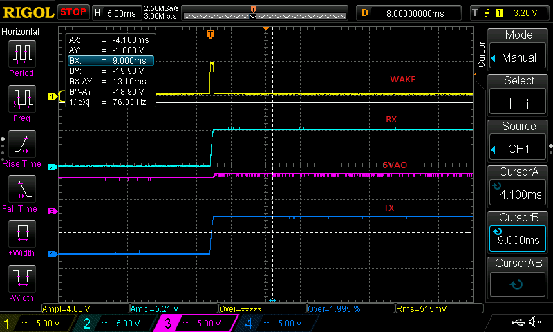
    Above looks all OK to me. (Slopes at wake up are a bit different compared to your picture.)

    We use a 50V stack voltage.

    Below the picture with the wake up againt the RX Pin (in total) Also 5VAO in this picture.

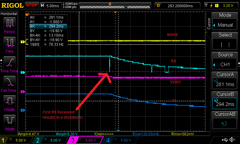
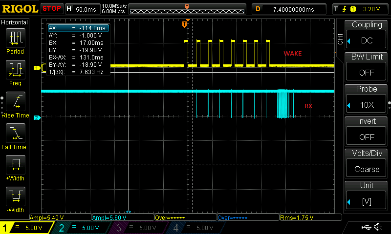
    From this picture I zoomed to the first and the last part in below pictures:

    In the last picture you can see that after receiving the first communication the battery controller goes into shutdown with the resukt no more communication possible. I checked the normal behaviour of the GUI. It normally send up to seven times the same byte to the battery controller. after that some other data is send.

    If i force WAKE to be high during the first part of communication with the GUI (until it detects the number of boards) and the make it low again. I can communicate with the battery controller without a problem.

    I have tried this on more than one board.

  • Hi Leo,

    To help debug the issue further, would you be able to do the following 3 tests? Each should be done separately.

    1. While waking the device as you have described, monitor and capture COMMH+/COMMH-. See if there is any data being sent on these lines. If not, then make sure that VP, VDIG, VIO, and VDD are all reaching their POR thresholds properly, as this means the device does not reach the WAKE propagation stage.

    2. Try sending a series of WAKE pulses (similar to what Vish has shown in his scope capture), and see if the device still reacts the same:
    -Try 5 pulses of 2 ms with 10 ms in between pulses (as shown in Vish's scope plot). See if the device is able to communicate.

    3. If that works, then try the following:
    -Try 5 pulses of 500 us (as shown in your plots) with 3 ms in between. See if the device is able to communicate.

    This will help us to better determine where in the wakeup sequence you are experiencing issues, and if the propagation of the wakeup tone to the devices is occurring properly between devices.

    Thanks,
    Vince
  • Hi Vince,

    Point 1 I know I get wake signal on the differential bus to the next part I already checked that.

    Point 2 With the 5 pulses it is still not able to communicate (I even increased to 100 pulses but had the same result)

    I still have the same behaviour. I believe the battery management IC is awake. But it receives something on which it decides to sleep. If we keep the wake pin high during the initilization of the gui and then make it low the communication will work until we press the button reinit serial comm. After this the IC is in sleep again.

    I have tried to reproduce this problem on the 76PL455EVM. I partly succeeded in reproducing. If you remove the connection to pin6 of J3 (wake from the FTDI) you will never be able to communicate with the BMS ?????. The difference between this and our own board is that our own board goes into shutdown after receiving the first byte. The EVM stays awake.

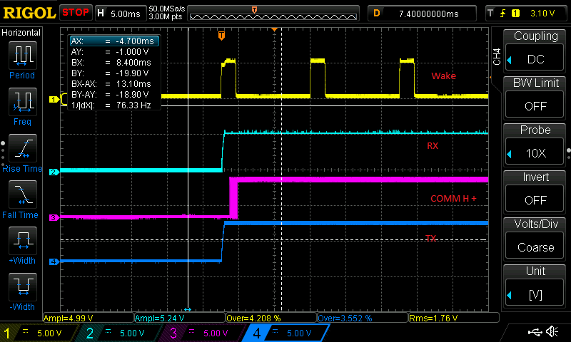
    Below is measurement on the EVM (with Pin6 of J3 still connected)

    I have seen on the EVM that whenever there is an wakeup pulse, a byte is received, and then the next wake pulse (this repeats for a number of times) and then the communication starts. There seems to be a relation between Wake up and the byte received. (It this true?). The datasheet does not mention any relation between wake and RX. It also does not mention you need to send more then 1 wake up pulse!

  • Hi Leo,

    To answer the questions you asked:
    1. Yes, if you remove the wake pin connection of pin6 of J3 (wake from the FTDI), you cannot wake the device, and so you cannot communicate with the device, as it was never awake. This is can be seen in the datasheet.
    2. You do not need to send more than 1 wake up pulse to wake up the device. This is only useful when there is more than one device stacked together. If there is more than one device, the sample code will send a powerdown signal a number of times (equal to half the number of devices in stack), then send a number of wake signals (equal to half the number of devices in stack) to ensure all devices are powered up.

    In your reply, you mentioned that you are sending the signal from the PC to the ~WAKE pin (pin6 of J3) which is designated as an inverted pin. This means you are not inverting the WAKE signal you are sending properly. As per the datasheet: "The WAKE signal from the PC is inverted on the bq76PL455EVM before being directed to the bq76PL455A-Q1." You must invert your wake signal in order to properly wake the device when using an inverted pin such as ~WAKE on the EVM.
  • Hi Vince,

    1 The EVM was already awake when starting the communication. The Vp and Vdig were present. Are you able to test this with the EVM? (Disconnect pin 6 from J3 or pullout the contact from the FTDI connector). What is your result?

    2 Ok so 1 wakeup pulse should be enough. I know my device is in wakeup state but for some unknown reason it goes into sleep after receiving the first byte.

    I will try to invert the Wake signal from the FTDI and connect it to our own board tomorrow. I will let you know the results.

  • Hi Leo,

    To answer your questions:
    Leaving WAKEUP unconnected or disconnecting it during operation is outside of the design specifications (see the Pin Functions table in the datasheet), and will likely result in unintended behavior. This may be part of what you are seeing in question 2.

    Let me know if the suggestion fixes the issue, or if you need any further assistance!

    Thanks,
    Vince
  • Hi Vince,

    I have tested again with the EVM.

    This time i disconnected Pin6 of J3 from the FTDI, but i put a pullup from pin 3(VCC) to Pin6 (WAKE).

    If i do this the wakeup pin is defined as zero. After powerin the board i manually give a pulse on the wake pin (a short between pin 1 and pin 6). After verifying the board is awake (measuring VP1) I tried starting the GUI. This gives exactly the same result as on our own board. The communication will not start and the battery chip goes into sleep.

    So the EVM does exactly the same thing as our board!?.

    So my issue is not fixed yet. There is something very specific which is needed during the starting of the serial communication. (To remind you if we tie the wakeup pin high, the communication is always starting. But we cannot put the chip into sleep).

    So additional hints, idea's to test are welcome.

  • Hi Leo,

    Would you be able to test the following on your board and let us know the results? This will help us to narrow down other potential causes for this strange behavior:
    -Measure the VIO voltage of the PL455 before the microcontroller/host is powered on or connected, but after the PL455 is awake. [Certain inputs (GPIO, FAULT_N, RX, and TX pins) must be less than VIO+0.3V]
    -Do a COMM_RESET and attempt communications

    Thanks,
    Vince

  • Hi Vince,

    VIO is 5.3V after wakeup before we start communication.

    Please note, we are not using a CPU directly. We use a RS485 to TTL conversion IC for the serial interface. This converter IC is always connected to the VIO on the secondary (battery) side (See schematic at the start of this thread).

    If i force the communication to start (by a long wakeup pulse (10seconds)) i am able te run with the GUI. ?If i press the Reinit communication button in the GUI (second tab), I can see a COMM_RESET is done and after that the same serial sequence as when starting the GUI. The result is also the same. The device shuts down although it was communicating normally before I pressed the reinit communication.

    So in Short: When i give a wakeup pulse of 10 seconds, And i start the GUI during that 10 seconds I have communication. Until I close the GUI and start it again or I press the reinit comm button. This can also be reproduced on the EVM by disconnecting Pin 6 of the FTDI and putting a Pull up on the open input of WAKE.

  • Hi Leo,

    I would recommend checking the functionality of the components related to the WAKE/communication lines, and ensure none are damaged. Any disconnect or fluctuation of the WAKE line, even temporary, can cause issues like those you are seeing each time you attempt to communicate. As your design works when WAKE is forced high throughout the communications process, there is likely something causing fluctuations on VIO or VP during each communication. So it will be beneficial to ensure that there is no change in VIO, VP, or VDIG when communications are sent/received.

    Thanks,
    Vince