This thread has been locked.

If you have a related question, please click the "Ask a related question" button in the top right corner. The newly created question will be automatically linked to this question.

BQ25504 - Transient voltage durring open-circuit voltage (MPPT)

Other Parts Discussed in Thread: BQ25504

Hi everyone.

I'm having a serious problem with the BQ25504 and I need a little help. About the MPPT, the datasheet at 14 page says.

...the boost converter modulates the effective impedance of the energy transfer circuitry to regulate the
input voltage (VIN_DC) to the sampled reference voltage (VREF_SAMP). A new reference voltage is obtained
every 16s by periodically disabling the charger for 256ms and sampling a ratio of the open-circuit voltage.

My problem is, each time that the CI disables the charger, the voltage on Vstor drops. It is a big problem because, when this occurs, the Brown-Out Detector of my microcontroller reset it. I can't disable the MPPT because I'm using solar panels (the sun incidence is so much irregular).

I'm using a battery of 3,7V with 3800mAh. At first, I thought it was a problem in the battery. However, the problem occurs even with a fully charged battery. My circuit is exactly as the circuit of page 6 of datasheet.
I tried to put a supercapacitor at Vstor pin in parallel with the Cstor and Cfltr but the voltage transient don’t disappeared.

Have anyone any idea to help me to put a finish on this voltage transient?
And sorry for my english, its not very good yet.
Thanks.

  • Hello Lenardo,

    Could you provide a scope capture of what the voltage at the VSTOR pin is doing during the sampling period?

    What is the brownout voltage of the MCU? Also what is the nominal load of the MCU?

    Also how close is the VSTOR pin and the capacitors that are placed on it to the MCU?

  • Hello Ryan.

    Sure. These are the pictures of "Vstor" when the transient happens.


    and

    The load is about 22mA. 

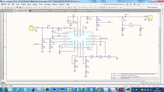
    If necessary, it's the schematic:

    I use a Atmel 644PA µcontroller. In this guy, we can easily change the value of Brown-Out. When I use 2,7V, the µcontroller always resets. But when I use 1,8V it stops reset. So, this reinforces the distrust under the transient.

    And I'm sorry but I dont understand about what capacitors are you talking. Cstor and Cfltr or the decoupling capacitors of MCU?

  • Hello Leonardo,

    I would recommend testing with a larger Cstor capacitor to help manage the transient on the VSTOR pin. The value that you have is deemed a minimum value.

    Since you are trying to supple 22mA for 256ms without allowing the voltage on the VSTOR pin to droop below the brownout of 2.7V  4.7uF as you have found is insufficient capacitance. Since you have found 4.7uF to work for a brown out 1.8V I would recommend looking at increasing Cstor by 2X or 3X and see if the brown out continues at the 2.7V level.

    This other post also discusses transient related issues on Vstor. While they are not the exact same it provides some recommendations for how to address the issue.

    http://e2e.ti.com/support/power_management/battery_management/f/179/p/332256/1159055.aspx#1159055

  • Based on your resistor values, I see that you have VBAT_OV=4.21V, VBAT_OK=3.75V and VBAT_OK_HYST=4.17V and VBAT_UV=1.689V.  VBAT_UV is below the 2.2V minimum value.  Also, with tolerances, the VBAT_OV and VBAT_OK_HYST thresholds will overlap and VBAT_OK might not trip as VSTOR is rising.

    Regarding your transient issue, I agree with Ryan about adding more capacitance on VSTOR.  Also, are you certain the load transient is only 22mA?  The drop in voltage suggests much higher.  The low impedance capacitance on VSTOR will first try to absorb the transient but then the storage element on VBAT should be able to handle it, less the dc voltage drop caused by the elements internal resistance and the resistance on the VSTOR to VBAT PFET.  Doing a simple V=IR computation with your over 1V droop and 22mA means your resistance in is R=1V/22mA = 45ohm? 

  • Hello guys.
    Alright, let me divide the answer:

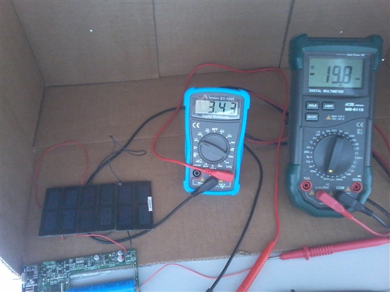
    Jeff, I took this picture to show what I'm doing.

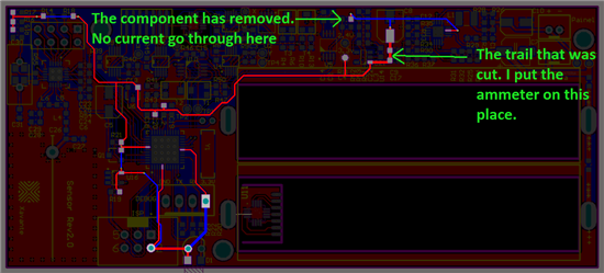
    The amperemeter (green) is showing the current leaving the battery when there is no light in the solar cell. This is the largest current drawn by the circuit. The blue one is the voltmeter and is measuring the Voltage on the battery.

    Jeff, thanks for the advice with the VBAT_UV. I just change the resistors to Ruv2 = 5,9M (R34) and Ruv1 to 4,22M + 0 (R36 + R37). Now I have a VBAT_UV = 2,99V (is that right?).

    Jeff, about the VBAT_OK, I will reduce the VBAT_OK_HYST to leave this "tolerance zone" that you are warning me. Later I tell you the result of this change. Thanks Again.

    Jeff, I don't understand why my battery is allowing the voltage drops so deep. And in this part of the problem I did a long test. Please look at the file that I attached on this post.

    0268.Transiente do carrregador.rar

    I changed the intensity of the light in the solar cell and the result surprise me. What is happening between 1,6V and 2,28V in VIN_DC pin and why my battery is not holding the voltage in the VSTOR???

    Ryan, this

    "2. Connect the system directly to the VBAT pin, thereby bypassing the internal PFET's undervoltage protection, which may not be necessary for supercap. This eliminates the impedance of the internal PFET."

    unfortunately i can't do because I really need a undervoltage protection.

    But about "Increase the 4.7uF ceramic capacitor on VSTOR", i will try and will repeat the test that I attached on this post about the waveforms. As soon as possible I will post the results here, but, if you can, take a look at this waveforms to help me to understand what is happening.

    Thanks a lot, guys...

    Leo

  • Was the ammeter in series when took the scope shots?

  • Then, based on the measured voltage droop, either your series resistance is higher than expect or the load transient is higher.  Do you have a current probe for your oscope with which to measure the load transient?  If not, do you have a small resistor that you can place in series and take the voltage difference as the current? 

  • Jeff, yes I have a small resistor to put in series to take the voltage. But my question is, Where do you suggest I put the resistance? After the VSTOR pin, right? But before what? Do you suggest that the problem is the resistance of the trail of my PCB?

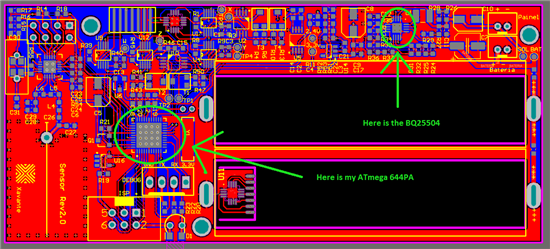
    This is my PCB:

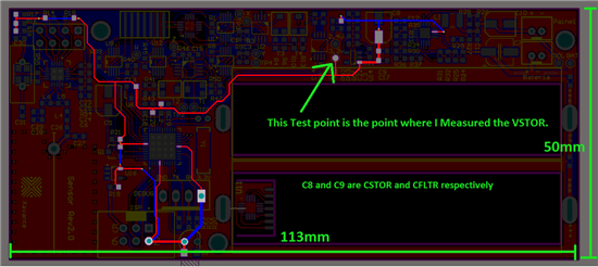
    And this is the trail:

    I tried to get "signal integrity" to estimate what is the impedance of the trail, but unfortunately it will take a little While.

  • Those traces are quite small for power rails.  You might be able to read the resistance of that trace from one point to another using your DMM set to resistance.

    You can measure the current anywhere in the path.  The voltage will be different at different points.

  • "Those traces are quite small for power rails".   You suggests that I enlarge those traces on my next PCB?

    Sorry but I don't Know what ''DMM" means. 


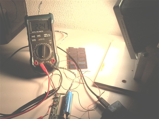
    About the test of current,


    and the result was:


    As you can see, the current was 22,4mA.

    The largest consumer of power on my board is this guy:


    https://www.sparkfun.com/datasheets/Components/SMD/nRF24L01Pluss_Preliminary_Product_Specification_v1_0.pdf


    The higher current drained by it is 13mA at 3V. There is no other component that drains a value close to this. Só I believe that this value match with our project.

    So, the transient voltage on VSTOR remains a mystery.

  • DMM is digital multi meter.

  • Hi guys.

    I had a problem to find some supercapacitors. But finally I found it and did the test.

    The 0.2F supercapacitor that I had wasn't strong enough to hold the voltage transient. When I found others supercapacitors, I put 4 of it in parallel (0.8F) and they were strong enough to hold the VSTOR above the minimum voltage necessary. So, the microcontroller is no more reseting.


    But now I have another problem because supercapacitors are very expensive. I am trying to find other solution to this problem.
    If I understood correctly, when BQ25504 is sampling the ratio of the open circuit (16 to 16 seconds), the VSTOR pin is NOT powered both VIN_DC and VBAT. This is the reason why the transient happens. Putting a supercapacitor probably will solve the problem. But I am trying to find another way to supply the VSTOR pin during this moment. Does not seem reasonable put a supercapacitor in a circuit that have a powerful battery available.
    I am thinking about put a transistor between VBAT e VSTOR and find a way to regulate the Gate to open only at the moment that BQ25504 is sampling the ratio of the open circuit (to supply the circuito with the battery and without a supercapacitor).

    As you can see in my schematic, I am trying to elaborate a circuito to put in the "red circle" to solve the problem without a supercapacitor. My first option is put a transistor but I am evaluating "how" and "the consequences" of this modification. Can you help me to find a solution?
    Thanks.

  • The PFET between VSTOR and VBAT is closed whenever VSTOR > VBAT_UV threshold and will not open simply because the input is MPPT sampling.  Switching stops during MPPT sampling.  I do not recommend allowing VSTOR to collapse below 1.8V otherwise the IC will enter cold start mode.

    I am puzzled as to why your charged battery cannot supply the load transient.  As I mentioned before, either the transient is higher than you think or the path from the battery to the load is very resistive.  You can use the equation I=C*dv/dt to compute the transient current (I) for the given voltage drop (dv) and transient (dt).  You can approximate your  battery's equivalent capacitance using

    Battery AHr x 3600 s / Hr x V(BAT)nominal = 1/2 x C x (Vhi^2 - Vlo^2)

    The equations above do not account for high resistive path to the load.

  • Trying to figure out why this transient happens I came across the following situation:

    My board have a debug header to connect the communications pins of microcontroller to an external "Serial-to-USB converter". So I am able to communicate with the microcontroller During its operation.

    When I left the debug supply pin opened, the transient happens, but when I left the supply pin closed the transient disappears.

    It means that the Serial-to-USB converter can supply the system better than the battery So, it indicates that the battery probably can't handle with the change of load current very well. I dont have the "Slew Rate" of the battery and I am trying to discover a way to measure it, but probably it is the problem. 

    About the capacitance of battery, we already had a distrust with the quality of this battery, The tests I'm doing are reinforcing this distrust. I am trying to reproduce the problem of transient (it don't happens always) to put two or three batteries in parallel. If the transient disappear too, the problem will probably be solved.

    And about this equation, I have some doubts. My battery have 3,8Ah of nominal capacity and 3,7V of nominal voltage. So the equation is

    3,8 x 3600 x 3,7 = 1/2 * C  * (Vhi^2 - Vlo^2)

    is it right?


    I measured the resistance of path load-battery by measuring the drop voltage between they but no decrease was observed. There is another way (more eficient) to discover the resistance of the path that you recomend?

    And reading the datasheet again, a doubt arose:

    If  BAT_OK_PROG = 3,75V and VBAT_UV = 3,00V, I have a "windonw" of (3,75 - 3,00) = 0,75V. what kind of behaviour can I expect from BQ25504 in this windonw?

  • The equation appears to be correct.

    BAT_OK is a status signal.  It does not change IC operation and simply reports whether the VSTOR voltage is above or below the user set threshold.  When the battery falls below VBAT_UV, the PFET between VSTOR and VBAT opens to prevent the storage element on VBAT from discharging below VBAT_UV.  Any system load on VSTOR will not have the "help" of the storage element on VBAT.

  • Look at this: 

    I changed the resistors to this:


    ROV2 = 5,6M and ROV1 = 4,5M  (VBAT_OV = 4,20V)

    RUV2 = 4,99M and RUV1 = 4,53M  (VBAT_UV = 2,26V

    ROK1 =3,3M,  ROK2 = 4,22M  and  ROK3 = 2,61M (VBAT_OK_PROG = 2,84V and VBAT_OK_HYST = 2,83V)


    But when I turn off the light over the Solar cell and the voltage of the battery drops below 2,84V, the voltage of VSTOR drop to 1,8V (seems cold start) and just back to the battery voltage if I put back the light over the solar cell.

    Seems that, when the voltage follow below the VBAT_OK_PROG. the BQ think that the voltage trip the UV and open the PFET.

    But if the battery have 2,84V, why the BQ enter in "cold star" mode?


  • rectifying:

    RUV2 = 4,99M and RUV1 = 4,53M  (VBAT_UV = 2,62V)

  • Jeff, one more think.

    When the voltage on baterry follow below Vbat_UV it supossed to open the PFET betwen VSTOR and VBAT. But why the voltage at VSTOR ramains in 1,8V? Is it "Cold Start"? If it is, how can I fully open the PFET to avoid any discharge?

  • If VSTOR is at different voltage than VBAT then the PFET is open.  Keep in mind there is a diode from VSTOR to VBAT.  Is it possible that a transient has reduced the VSTOR capacitor voltage below VBAT_UV (because the impedance to the battery is high), causing the PFET to open?  If so, then you will have to wait until VSTOR rises above VBAT_UV for the PFET to close again.

    By the way, if you are in cold start, the MPPT does not function. 

  • Jeff, when you said:

    "If VSTOR is at different voltage than VBAT then the PFET is open"

    are you mean VSTOR > VBAT or VBAT > VSTOR???

    As I understood from datasheet, if VSTOR falls below VBAT_UV then the PFET will remains off (open), no matter what.

    when you said:

    "If so, then you will have to wait until VSTOR rises above VBAT_UV for the PFET to close again."

    But the problem is that the PFET is always close. It don't open and the battery is always being discharged.

  • The PFET should only open if VSTOR is less than VBAT_UV.  The diode from VSTOR to VBAT_UV will keep VBAT_UV a diode drop below VSTOR.  Can you remove the input harvester and connect a power supply at VSTOR and force the voltage above and below VBAT_UV?  That will confirm whether the VBAT_UV resistors are sized properly and are not being resized by the parasitic resistors from residual flux.

  • Hello Jeff.

    I was traveling. Just came back.

    I took the battery and put a Power Supply. 

    The yellow one is the Power supply voltage (on VBAT PIN);

    The Blue one is VSTOR pin;

    The pink one is VBAT_OK pin;

    This is the scope:

    I changed the values ​​of resistors. Now I have:


    RUV2 = 4.99M
    RUV1 = 4.53M
    VBAT_UV = 2.62V

    ROV2 = 5.6M
    ROV1 = 4.5M
    VBAT_OV = 4.20V

    ROK1 = 3.3M
    ROK2 = 4.22M
    ROK3 = 2.61M

    VBAT_OK_PROG = 2,84V
    VBAT_OK_HYST = 3,83V

    VBAT_OK_PROG seems very good.

    VBAT_OK_HYST seems good.

    But VBAT_UV and VBAT_OV seem to be not working. Why the battery is not being cut?

  • VBAT_OV will only stop the boost from switching if you take Vpowersupply=VBAT=VSTOR>4.2V. 

    The internal FET between VBAT and VSTOR should open when Vpowersupply=VBAT=VSTOR<2.62V.  There appears to be a some activity around 2.62V. 

    For testing VBAT_UV, it should not be unless the power supply you are using can sink current.

  • "VBAT_OV will just disable the boost converter. OK with that.

    The internal FET between VBAT and VSTOR should open when "Vpowersupply=VBAT=VSTOR<2.62V"

    But it's not happens. There is this activity around 2.62V, ok but for some reason, the BQ starts to switch the value of VSTOR and, as you can see in the scope pictures, below 2.62V, the voltage remains falling. I am puzzled with that. It's a big problem because our batteries are being damaged for deep discharge. We lost more than half of our batteries because of this.
    My power supply can sink current, it's not a problem. Besides, the deep discharge happens with the batteries, too. Is there anything I forgot to do to make VBAT_UV work and cut the battery?

  • Assuming the VBAT_UV resistors are the correct values, the only other issue I have seen is solder flux residue creating parasitic resistances that change the values.


    Does this happen on multiple boards with different ICs?  Have you tried replacing the IC on the failing board(s)?

  • Hi Jeff.

    The first prototypes of our boards are been made inside our own laboratory. Checking carefully, I found solder flux residue around the pads of BQs and the resistors that gave it the parameters of UV, OV, etc. I cleaned very well this pads and now I can see the Over_Voltage working. The Overvoltage expected was 2,62V but the BQ is opening the PFET between VSTOR and VBAT when the voltage of battery stay around 2,70V and 2,80V. this difference in voltage is within our limits, so, it isn't a problems. I don't know if it will solve the problem but seems to be helping. I'm still doing a tests in other 5 boards to confirm the results and for now, the overvoltage seems to work close the expected. But another problem arose.
    Please look at this video.

    http://www.youtube.com/watch?v=UbAagUqV-UU&feature=youtu.be

    This is our board. The osciloscope is showing VBAT (yellow) and VSTOR (Blue). When the solar cell stays without light for a little while, the BQ enter in "Cold Start Mode" even if the battery is full of energy. And it just comes out of this state if we put light over the solar cell again. In our application, we expect total darkness over solar cell for some hours. But we need the BQ to supply energy to the board with the energy available of the battery when it happen.
    So, my question is, there is a way to prevent the BQ from enter in Cold Start Mode when the voltage on solar cell is 0V and stay supplying the board with the energy available on battery?

  • This is very very critical for us.

  • If the voltage at VSTOR is > 1.8V, the bq25504 will not enter cold start.  You will need to decrease your load on VSTOR or increase the capacitance on VSTOR or lower the VBAT_UV threshold so that the battery stays connected and does not allow VSTOR to drop below 1.8V.

  • The load is not too high because the BQ starts normally when the light stars to shine (so I know that "load tied to VSTOR don't prevent the storage element from charging VSTOR within 45 ms typical"...)
    I already have put a super capacitor on CSTOR.
    VBAT_UV is 2,62V.
    It not happens just when the BQ is been turn on. It happens when the BQ is in normal operation (when VSTOR > 1.8V, in my case, when the VSTOR = 3.5V). When the light stops to shine during a little while, the BQ simply stops to supply energy to the VSTOR even with a fully charged battery and all my system fails.

    If there is 3,5V on Battery, why the BQ strangles the PFET and just allow it to supply 0,9V when the voltage on VIN_DC is about 0V? There is another kind of system that can strangle the PFET like this?

  • No.  The PFET is controlled by the VBAT_UV circuit.  If that is functioning correctly, the PFET should open.

  • So, who is the responsible for the behaviour of VSTOR Voltage in the last video that I posted? I have other boards that are showing the same problem:

    VBAT = 3.05V and VSTOR = 2.15V.

    VBAT = 3.60V and VSTOR = 0.63V


    It can't be a problem in my board because, only a change in VIN_DC can put on VSTOR the same Voltage that VBAT. It only can be something in BQ25504 system. But what?