This thread has been locked.

If you have a related question, please click the "Ask a related question" button in the top right corner. The newly created question will be automatically linked to this question.

BQ25504 EVM: Charging Supercap from 1V to 3V

Other Parts Discussed in Thread: BQ25504, BQ25570

Hello all,

I am simply trying to charge a 3V Super Capacitor from 1V up to 3V, and I am trying to figure out the most efficient way to do this using the BQ25504 EVM.

My input power right now is approximately 0.011 mW, which is quite low. (Input voltage ~0.345 V) The power pulses like a square wave every 6 seconds, with a 50% duty cycle. There is no load.

I have just a few questions:

1) Will this input power be enough to charge the super capacitor?

2) Right now, I assume that I must connect the supercap to VBAT, and VSTOR is open on the EVM.  Is this the correct circuitry, or is there something else I must do?

3) Would it be more efficient to start the supercap at ~1.8 V (Vstor_chgen) and start charging from there up to 3V, or does it not matter?

Thank you, I'm open to any and all suggestions for improved efficiency.

Brock

  • Regarding 1, with VSTOR<1.0V, the IC runs in less efficient cold start mode and requires as much as PIN(CS)=50uW to charge VSTOR to 1.8V and enter more efficient main boost charger mode.  Input power of 0.011mW is not enough power to exit cold start.

    Regarding 2, connecting the supercap to VBAT is the typical implementation.

    Regarding 3, yes.  That works best.

  • Jeff,

    thank you for your reply.

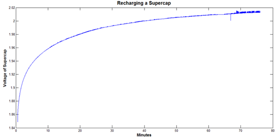
    I was able to increase the input power to about 0.35 mW on average.  I am having the problem where the super capcitor seems to charge quickly for the first 10 minutes or so, and then it seems to quickly slow down the charging of the super capacitor.  The input power to the BQ25504 remains the same, but the recharging rate dramatically slows down after about 10 minutes.  I've included a picture of this behavior below.  

    Any ideas what would be causing this behavior?

    Thanks,

    Brock

  • You are out of cold start mode.

    What is your VBAT_UV threshold?

    What is your VBAT_OV threshold?  

    Is there a resistive load on VSTOR or VBAT?

  • VBAT_UV and VBAT_OV are the default values on the TI BQ25504 evaluation board, which I believe are 2.2V and 3.1V consecutively.

    There is no resistive load on VSTOR or VBAT - only the super capacitor is connected to VBAT.

    Thanks,

    Brock

  • At VSTOR=2.2V, the PFET between VBAT and VSTOR closes, effectively shorting VBAT to VSTOR (as opposed to having VSTOR connected to VBAT through the body diode of VSTOR).  The IC should continue to charge at roughly the same rate but with a ~0.6V jump when the PFET closes.  

    Can you send a plot with LBST, VBAT, VSTOR and VIN_DC?

  • Unfortunately, I don't have the equipment to measure all the parameters at the same time, but I was able to measure them all separately and then put them on the same graph.

    Below, is a graph of LBST, VBAT, VSTOR, and VIN_DC. As can be seen, LBST and VIN_DC are essentially the same, but because I measured the two values at different times, they do not overlap correctly. Also, I precharged the supercap to about 1.8V, and then connected it to VBAT. As can be seen, there is no charging.


    Here were the order of events:

    1) Discharged VSTOR to a few millivolts.

    2) Connected VIN_DC source

    3) Connected super capacitor (precharged to 1.8V) to VBAT

    4) Measured VIN_DC/VSTOR/VBAT/LBST consecutively

    Any idea what might be causing the super capacitor not to charge?

    Thanks,

    Brock

  • From this graph, it appears that you do not have enough input power to exit cold start because VSTOR has not risen above 1.8V.  

  • What is the leakage current of the supercap?

  • Hello Jeff,

    The leakage of my supercap is rated to be in the 1's to 10's of microamps.  Yes, it looks like there is not enough input power to get out of "Cold Start" mode.  Do you know if there is any way at all of helping the supercap to start charging?


    Or is increasing the input power the only way to fix this?

    Thank you,

    Brock

  • Have you considered moving to the bq25570 and using the circuit as explained in the article below:

    http://www.edn.com/design/power-management/4422103/Fast-charging-a-supercapacitor-from-energy-harvesters

  • @Jeff F 
    i really need u 
    plz contact me as soon as possible and thank u :) 

  • Jeff,

    thank you for your suggestion! I hadn't considered the BQ25570. I read entirely through the datasheet for the BQ25570, and I couldn't see a clear advantage over the BQ25504.  Could you explain your thoughts for using the BQ25570?  Is it in conjunction with the circuit in the EDN article that you sent (pictured below)?

    Thanks,

    Brock

  • If you click through the 4-page article, you will see a comparison of the circuit above, to the bq25504 powering a super cap and then the bq25570 powering a super cap. Basically, if put the supercap on the output of the 570's buck converter, the cold start circuit and main boost charger are isolated from the super cap by the buck.

  • Jeff,

    thank you very much for this suggestion.  I will investigate the BQ25570 as an alternative solution.  I may also try a PFET between the supercap and VBAT, with VBAT_OK as the trigger.  Do you think this is a possible alternative as well?

    Many thanks,

    Brock

  • The PFET between supercap and VBAT pin will turn on quickly and collapse VSTOR as VSTOR tries to charge the supercap.  You would need to add a very slow soft start RC circuit on the PFET.

  • Jeff,

    I recently received the BQ25570 EVM, and it has worked wonderfully so far.  Thank you for this suggestion.  I simply placed my super capacitor at the VOUT terminal, shorted VSTOR to VBAT, and applied my source to VIN_DC.

    As my 3V 4F super capacitor was charging yesterday, I noticed some interesting behavior.  The super capacitor voltage seemed to spike up and then drop quickly every second. Here is a zoomed in graph of what was happening.

    Do you know if this is normal behavior for the VOUT terminal of the BQ25570, or if this is due to some sort of mismatched RC constant, or something like this?

    Thanks,

    Brock

  • I expect some switching ripple but more consistent than shown above. Can you use an oscope to zoom in on VSTOR, LBUCK and VOUT over 3 of the different sized pulses?

  • Jeff,

    I recorded these 3 voltages from VSTORVOUT, and LBUCK simultaneously.  Below are the results.  For LBUCK, I measured from the TP3 node on the BQ25570 EVM.  I'm not sure if this was the correct node or not, but on the schematic online it appears to be correct.

    I am using a 3V 4F Super Capacitor, which is connected to VOUT. The super capacitor has internal resistance of 0.3 ohms.  I have VBAT and VSTOR shorted together.  The input source to VIN_DC is definitely varying by time.  I included a graph of what VIN_DC looks like.  The graph below was measured at a different time than the graph above.

    Might my input to VIN_DC be a cause for the unstable charging for my supercapacitor?

    Thanks,

    Brock

  • The LBUCK node doesn't look correct.  It should be pulsing well above 0V.  The waveforms are reasonable.  VIN_DC will have repeating pulses up to the sources open circuit voltage every 16s.  From your plot, it appears your source's open circuit voltage is 2.5V and you have the MPPT voltage set to ~1.9V.  The down pulses show your source collapsing at random times but then recovering.