This thread has been locked.

If you have a related question, please click the "Ask a related question" button in the top right corner. The newly created question will be automatically linked to this question.

BQ25505 - charging battery with piezoelectric

Other Parts Discussed in Thread: BQ25505, BQ25504

Hello,

I read bq25505 datasheet, EVM datasheet also. I have few questions about bq2505 and how this IC works with piezoelectric element.

1. What AC/DC rectifier do you recommend for piezo energy harvesting application? Please take under consideration current and voltage losses on the rectifier. Could you please give an example of a small package rectifier?

2. What is the best way to make an rectifier that would lose as low power as possible? Is there a more efficient way that using schotkey diode or mosfets as rectifier?
Is it recommended to use zener diode after rectifier? Could you please give example of recommended zener diode that would have very small reverse (leakage) current under normal piezo energy harvesting operation?

3. Is there any requirement as far as protection on the input of the charger is considered?
Is there a solution (for example to use proper input capacitor) so that every piezo energy impulse (after every bend of piezoelectric) could be transferred to battery (charging battery)? For example, when piezoelectric is bended every 10-20 seconds, there is big power loss on the input side (input capacitor leakage, zener protection diode) between bends.

4. How to, using function generator, simulate piezoelectric input to energy harvesting module?

5. What exactly MPPT set for piezo application? From where get proper reference voltage?
Could you please give me an example of application using V_bat_ok signal to connect/disconnect load from charger?

6. What kind of batteries are available for V_STOR output? Which have the smallest leakage current?
Could you please give me example of low leakage ceramic capacitor?

7. What is and how to measure ionic contamination?

8. Is it possible to connect V_Ref_sample to ground in order to transfer whole current to charged battery?

I will be very glad for your help with this subject.

  • Regarding 1, we recommended a rectifier of 4 discrete Schottkey diodes part number  MA4X79600LCT-ND.

    Regarding 2, to date there are no low voltage, ultra low Iq rectifier's on the market.  If the piezo can provide power higher than the bq25505 maximum recommended operating voltage, then a zener diode is required. 

    Regarding 3, MIcrosemi has the SZL line of zener diodes with 50nA reverse leakage but the highest clamp voltage is 2.4V.  Also it is possible to use an NFET with tight VTH as a voltage clamp as explained here: http://www.electronicproducts.com/Power_Products/Power_Management/Voltage_clamp_circuits_for_ultra-low-voltage_apps.aspx

    Regarding 4, a function generator set to high Z output with a series resistor can be used to simulate a piezoelectric generator.

    Regarding 5a, piezo electric generators typically do not have a maximum power point that is relative to open circuit voltage like solar and TEG.  So, it is typically recommended to set the maximum power point (i.e. lowest input voltage before bq25505 stops switching) as close to the charger output (VBAT_OV) and peak current capability (200mA typical) without collapsing the source in order to maximize the boost charger's efficiency.

    Regarding 5b, with the bq25505, the /VB_SEC_ON signal is the inverse of the VBAT_OK signal.  You can use the /VB_SEC_ON signal to drive the gate of a PFET in series between VSTOR and the system load.  That PFET will have source tied to VSTOR, drain to system load and a large pull up resistor between source and drain.

    Regarding 6, the battery would connect to the VBAT_SEC output not VSTOR.  Low leakage ceramics are typically the best dielectric like X7R or COG type.  Thin film rechargeables have the lowest leakge current but they are hard to find.  Several of the newer, low power LiIon batteries have low leakge.

    Regarding 7, higher end board assemblers have board washing machines that measure the ionic contamination in the wash water.

    Regarding 8, no.  The VREF_SAMP voltage is the voltage to which the MPPT circuit regulates VIN_DC in order to prevent the input source from collapsing.

  • Another zener option: Vishay's  BZT52 series with 100nA leakage.

  • Can you provide more details about your piezo source (max voltage, max current, impedance, resonant frequency) and end application?

  • First of all thank you very much for your answers. They are very helpfull.

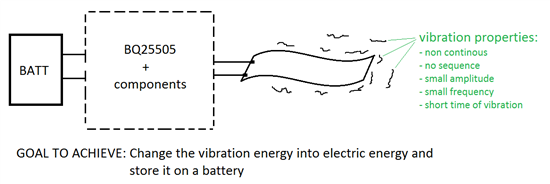
    The problem is that I still don't know which kind of piezo source I will use in my final project. I am still searching for the best solution that is why I can't say any details about my piezo source. But I can say about the final application. I am interested in building a device that will change the vibration to electric power which will be stored on the battery. Please have a look at the image below that describe the idea.

    I will be very glad for your help.

  • Do you intend for a partially charged battery to always be attached so that the bq25505 never goes into cold start? If so then the rectified output of the piezo needs to provide at least 100mV.   If not, then you will need to select a piezo that can provide the minimum VIN_CS and PIN(CS) so that the bq25505 can exit cold start.  

  • Thank you for your answers Jeff.

    In our application battery is going to be always connected to bq25505. I understand that bq25505 goes into cold start (stops working) when voltage at Vin_dc (on the bq25505evm connected to Vin_cs) drops below 100 mV for more that 16s (sampling time).

    1. Is it possible to connect output of the battery (always at voltage higher than 330 mV) to pin Vin_cs so bq25505 never stops working? In this configuration is it possible to transfer whole energy from piezo to battery?
    2. Our piezo would be bended one time every 30 s, so on the input side voltage would occure every 30 s. Piezo is capable of providing enough energy to charge the capacitor to voltage more than 330 mV. Would bq25505 transfer energy from this capacitor to battery and not pull to ground? (I have noticed, that when I start bending piezo, voltage on the input does not increase to more than 330 mV for about 10 sec (on average). Then it suddenly increase to for example 0.8 V and stays at this level for some time. I believe it has something to do with mppt).
    3. Are there any available chargers that would put any occurred energy on the input to the output?

  • The bq25505 is in cold start if the voltage on VSTOR is below 1.8V.  In cold start, the voltage on VIN_DC is clamped to about 330mV and no other circuitry (MPPT, VBAT_OK, etc) functions.  If your battery will never drop below 1.8V then the bq25505 should never be in cold start.  There is no VIN_CS pin. 

    Since your piezo is only providing power every 30s and the MPPT circuit is active every 16s, I think there could be a synchronization problem.  I suggest moving to the bq25504 which allows you to disable the MPPT circuit. 

  • Dear Jeff F,

    Thank you for your answers, they were very helpful.

    However I still have some more questions:

    1. In http://www.ti.com/lit/ds/symlink/bq25504.pdf is information, that VIN_DC capacitance should be “scaled according to the value of the output capacitance of the energy source”. How can I properly calculate a vin_dc capacitor value? Our piezoelectric capacities are from 1 nF to about 20 nF. Does this capacitance relay on the piezoelectric frequency? Does this frequency impact the cut-off frequency from R-C filter created by charger and piezoelectric capacitance?
    2.  I know that frequency of generating signal is vital. In our application (as mentioned above) the frequency is less than 0,01 Hz. In this situation, the capacitance of piezoelectric is a problem – in most of DC application there would be no current flowing through capacitor. Do you know any solution for this? I would like just to remind, that we would like to harvest energy from piezoelectric, not use this as a sensor. Is it possible to decrease the value of capacitor by using thinner piezo foil? I however it results in lower energy production. Could you help me find the solution?
    3. Is it possible to calculate the input impedance of bq25504 in order to simulate the system in spice program? On the input of charger is R-C divider, and we would like to get rid of phase shift (current is not in phase with voltage) and use an inductor. Do you maybe know a solution for this?
    4. When our piezoelectric is bended, it generates a bunch of frequencies (I have seen them on oscilloscope using FFT). How to calculate the most important frequency (that would be later used in calculations)?
    5. Our piezoelectric does not bend the same way every time – generated frequencies differ from bend to bend. When MPPT in bq25504 is disabled, is there any way to harvest energy in more optimal way?
    6. Our piezoelectric is not able to generate in one bend enough energy to exit cold-start. How to lower energy necessary to start charging battery?
    7. When charging process starts (bq25504 exits cold-start) it will consume more than 1uA. How to exit working mode and return to cold-start (in this mode charger does not consume more than few nA)?
    8. Is it possible to change input impedance of bq25504 in order to lower the cut-off frequency od R-C divider and this way increase generated voltage amplitude?

    If you have any suggestions (like last about using bq25504 in order to disable MPPT, which helped us a lot) please do not hesitate to write it.

    Thank you very much in advance for all your help!

  • Regarding 1, voltage at VIN_DC needs to be above the input regulation voltage threshold long enough for either the cold start circuit or the main boost charger to complete at least one switching cycle. The switching frequency could be as fast as 1MHz and will vary depending on the voltage across the inductor and the peak inductor, which varies as explained below.

    Regarding 2, with MPPT disabled but VREF_SAMP held at a voltage that still allows the input regulation circuit to work, I suggest that you size the capacitor so that it eventually charges above that threshold voltage, gets drained by the boost converter and then recharges.  The threshold level should be close to 1V if possible, which if where the charger's efficiency gets relativity higher.

    Regarding 3, the boost converter has a FET (with specification Rdson) that pulls current to ground through the boost inductor.  While the peak inductor current is 200mA typical, the charger steps up the inductor current in three steps of approx 50mA for 3 cycles, then 100mA for up to 2 cycles and then 200mA if the input voltage hasn't dropped below the input voltage regulation threshold.  So the initial input impedance could be as high as the boost inductor inductance plus VIN_DC/50mA,  The cold start circuit input impedance is much higher but is it not spec'd.  Initially, the cold start circuit will clamp VIN_DC to 0.3V.

    Regarding 4, I feel that you will need to low pass filter the piezo output with a large capacitor on VIN_DC so lower frequencies are better.  The charge requires a DC input voltage to operate.

    Regarding 5, as mentioned in the datasheet, the optimal way to operate is by installing a partially charged battery so that the IC's main boost charger can be powered from VSTOR, thereby bypassing the cold start circuit. With MPPT disabled and a reference voltage applied to VREF_SAMP, the IC will then pull current from the input capacitor until the voltage on that capacitor drops below that reference voltage.

    Regarding 6, to bypass cold start, you might consider a circuit like the one in the attachment, assuming the voltage levels are high enough to turn on each FET at the appropriate time.  This may require using a super cap instead of battery on VBAT as you would by tying the output of the piezo directly to the storage element (through a diode). 

    Regarding 7, the IC is in cold start whenever VSTOR is below VSTOR_CHGEN~=1.8V

    Regarding 8, see earlier responses.

  • Hello Jeff F,

    I have used the BQ25505 in one of my designs. I have a query regarding the cold-start circuit of the IC.

    As per datasheet of BQ25505, minimum power required to exit the cold start circuit is given by below formula:

    In our case: the storage element leakage is 100 nA at 1.8 V and load on STOR during cold start is the load of Timer device which consumes 50 nA. Also, I have tried by removing the Timer load on STOR pin on the evaluation board as in that case there will be no load on STOR pin.

    If we consider the above values to compute the min. input power required to exit the cold start circuit:

    The min required input power comes out to be 5.4 µW with Timer as load on STOR pin and 3.6 µW with no load on STOR pin.

    One of the amorphous silicon solar cell that I am using have the following characteristics at 200 Lux light levels:

    Size of solar cell: 53 X 25 mm

    Voc: 4.5 V

    Isc: 20 µA

    Vmpp: 3 V

    Impp: 18.5 µA

    If we compute the input power supplied by this particular solar cell in near short circuit condition at 330 mV (input voltage during cold start operation) the input current will be around 19 µA.

    The input power supplied by this solar cell is 6.2 µW which is sufficient to exit the cold-start circuit.

    At around 300 Lux light levels, I am getting around 28 uA of current on solar cell when I have connected it to a pico-ammeter. However, in this condition also, we are only able to get 1.3 V on STOR pin.

    I am not able to understand as to why does the BQ25505 is not able to exit cold-start in normal lighting condition?

    Please do let me know for any other information required to understand my question.

    Regards

    Prateek

  • Is the pico-ammeter installed during this test? If so, please repeat without the pico-ammeter. Also, what is the capacity of the storage element? If it is a supercap, the leakage current may not the same at 1.3V and 1.8V. With no storage element on an EVM (only the 100uF capacitor on VBAT) that I randomly pulled from stock, the EVM starts up from cold start with 28uA of current.