This thread has been locked.

If you have a related question, please click the "Ask a related question" button in the top right corner. The newly created question will be automatically linked to this question.

BQ24032A OUT pins Oscillate

Other Parts Discussed in Thread: BQ24032A, LMR62421

Dear Support,

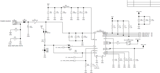
I am using the BQ24032A.  Attached is my schematic and a scope shot captured at the OUT pins of the system output.

I have a battery connected to the charger, USB only input.  The system load is a buck converter 3.3 LM3668SD-2833/NOPB, the 5V rail is unloaded, and another rail is unloaded.

If I enable the system load (via toggle switch), the output of the BQ24032A oscillates.  My first impression is that the USB can source the current somehow.  The strange thing is that the battery I connected has been fully charged, so I thought that if the system load requires more than what the USB can deliver, the battery would supply and compliment the system load requirements.  I don't think this is what is happening here.

I would expect the Battery supply the load current first then when everything is ok, the USB sustains the current needed for the design.

On the 3.3V rail would be some LEDs, a PIC24 Microcontroller, and other small peripherals, budgeted to around 150mA max.

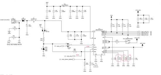
In my schematic if the processor can't come up, then it can't set 3 pins.  However, I designed it such that

CE is high when VBUS or AC power is connected

PSEL is high when VBUS or AC power is connected

ISET2 will be low.  This pin will only be set high when the process comes up.  It can't come up since it oscillates

As I am writing this, I will try blue-wiring the ISET2 high to see if this allows the USB 500mA to come up.

Can you please look at my schematic and let me know if I am violating a parameter for this chip?

Best regards,

Robert

  • I jumpered the ISET2 line to VBUS and the oscillations went away.  I think the USB 100mA current setting was starving the charger.  The confusing thing is that I expected the BQ to switch to battery immediately to supply the rest of the current to the load.  It is very likely my understanding of this charger is not correct, though most chargers I have used with Power path control do this.  Could it be a resistor setting?

    It would be nice if someone from TI could comment on why this is the case.   I realize the setting for ISET2 was defaulting to 100mA, however, the rest of the load current should have come from the battery in order to keep the load alive.  This was not the case though.

    Look forward to your comments

  • We have ordered an EVM and will be looking into this.  I suggest reviewing the DPPM resistor setting.

  • Hello Jeff,

    I have looked at the DPPM resistor, and I currently have 36.5K ohms.  My understanding  is I want to make VDPPM-SET = IDPPM-SET * RDPPM x SF

    The SF nominal is 1.150, IDPPM=100uA nominal.  This resistor sets VDPPM = 4.2V

    Based on the statement below, I set the resistor to that.  I could be mus-understanding the spec, but that's the value I placed.

    "3. The DPPM sustains the system voltage no matter what causes it to drop, if at all possible. It does this by
    reducing the noncritical charging load while maintaining the maximum power output of the adaptor."

    The conditions of my oscillations were:

    PSEL = HIGH

    ISET2 = LOW

    Battery connected 80% charged maybe

    USB connected 500mA nogotiated with host using FTDI chipset.  This chip has a register programmed to request always 500mA, though it is not guaranteed we will get it.

    I turn on the power switch (load connected to OUT pins) and voila! it oscillates.  When I switched ISET2 to high and repeat the test, no oscillations.

    All I want to make sure is that I have the correct values on my design.  Attached is my schematic, if you could please review it, I will be very greatful!


    Regards,

    RR

  • Jeff,


    I think I found another piece of information on the BQ datasheet Page 15 Charge control.  It reads

    "Charge Control
    When USB is present and selected, Q3 regulates the input current to the value selected by the ISET2 pin
    (0.1/0.5 A). The charge current to the battery is set by the ISET1 resistor (typically > 0.5 A). Because the charge
    current typically is programmed for more current than Q3 allows, the output voltage drops to the battery voltage
    or DPPM voltage, whichever is higher. If the DPPM threshold is reached first, the charge current is reduced until
    VOUT stops dropping. If VOUT drops to the battery voltage, the battery is able to supplement the input current to
    the system."

    In my case, RDPPM is set to 4.2 so, this is greater than the battery voltage of 3.7V nominal.  This could explain the oscillations

    The datasheet is not clear on what SF to use.  So I am using nominal values

    Setting VDPPM-SET  = 3.55V so it drops to or below the battery voltage, and solving for RDPPM, I get 3.55V/(1.150*100uA) = 30.9K  I will change the setting and try this.

    Rob

  • What is your load current profile? constant DC?  pulsing at a fixed frequency? etc.

  • Hello Jeff,


    The loads are 3 switcher, but I have not yet quantified it all.  My predictions are below based on modeling

    1. LM3668SD-2833  -3.3V rail buck converter load current is probably in normal operation less than 150mA

    2. LMR62441XMFE - 10 - 20V boost converter -  load current is about 30mA worse case 50mA at 20V

    3. LMR62421 - 5V boost converter.  Maximum load around 80mA

    Total current being drawn is constant at around 300mA total.

    Rob

  • Hello Rob,

    I am not able to recreate the problem on our EVM so far. Could you please send us your scope shot with VOUT and VBAT on the same scale?

    Also, what is the battery you are using for this testing? What is the capacity? Do you have other impedence connected to the battery?

    Regards,

    -Jing

  • Jing,

    I will have to capture the traces and send them to you.  Again, the conditions of my tests are:

    1. Lithium battery 2000mA-hr capable of 3A short circuit current.  The battery is connected directly to the charger, no other impedance other than a sense resistor 0.010 ohms for a Fuel Gauge is in series with ground.

    2. ISET2 Low

    3.I plug the USB ( I connect to a standard USB with a 3 or 6 feet cable) and I hear a faint hissing, and when I put my scope on OUT pins, it oscillates.  All the switchers are oscillating too since the OUT pin is the system power.


    By virtue of having ISET2 low, this implies the part is set for 100mA, so when the part comes up with ISET2 low, and battery connected, when I turn on a switch making physical connection from the OUT pins to the loads (3.3V switcher, 5V boost converter, and 10-20V boost converter), the part oscillates.

    I soldered a wire from VBUS to ISET2 to pull it up, and when I do this, the part starts fine no oscillations.  I am not sure if ISET2 needs to come up high or Low.  In my mind it should not matter because the part DPPM should switch to battery if no enough current is available for the system load.  That is not what is happening here.

    Please answer this questions:

    1. Do you have the same conditions as me?

    2. Have you looked at my schematic?  Do you seen anything wrong?

    3. Is it plausible the layout can be causing issues?

    The charger seems to charge the battery from a wall adapter, I can see the status pins working correctly.

    There are other weird issues happening if ISET2 is pulled high to VBUS (but no vbus or battery), and I connect AC Power, my voltage supervisor reset my processor.

    I think I will test it again, and send you screen shots.

  • Hello Rob,

    Regarding on 1, I did use the same condition as yours. I have also changed up the resistor value to match the ones on your schematic.

    Regarding on 2, I did not find any thing wrong standing out in your schematic.

    Regarding on 3, from your scope shot earlier, the output voltage is oscilating between 2  to 3V, I am not sure if the lay out caused the issue. I will need to see the scope shot of the battery voltage to further understand what part is doing.

    Regards,

    -Jing

  • Jing,

    Attached are the scope shots.

    Battery is the blue trace, and OUT pins of the BQ24032A is the yellow trace. The battery is fully charge and and the voltage level reads 4.2V.

    Conditions

    ISET2 is set low, battery connected, USB connected.  I turn on the switch, and this is what I get:

    The SWITCH has not been yet toggled

    Toggling the power switch

    Notice the blue trace the battery is set at 4.2V but the part seems to oscillate.  I am not sure if it is because the 3.3V switcher tries to come up too, and given that ISET2 is low, only 100mA is being requested.  I think the part is starving.

    I expected the rest of the current to come from the battery, but it is not.  I suspect that maybe other pins need to have different conditions?

    If I solder a wire from ISET2 to VBUS, I get this before I turn on the switch to the load.  This doesn't make sense to me because the maximum voltage I expect is 4.4V regulated at OUT pins.  It is larger than the battery voltage 4.88V. 

    ISET2 Pulled up to VBUS, and battery connected.  I turn on the switch to the load, and you can see the yellow trace drooping.  then it recovers.  I don't know if the battery took over, but the voltage supervisor doesn't reset my processor, and it turns ON.

    IF ISET2 is low, it won't even start and oscillates.

    I hope you can help me figure this out.  I am spinning the board, and ISET2 is now set to a pull up at 3.3V rather than VBUS.  I am not sure if this is normal operation or what, but something doesn't seem correct.

    Rob

  • Hello Rob,

    The battery voltage seems stay at the same level even when it is loaded. It doesnot look like the battery is outputing current. What happens if you connect the load to output with battery connected and input removed. What is the output voltage at this time? Does the battery voltage start to fall? I want to check if the battery FET Q2 is damaged.

    Regards,

    -Jing

  • Hello Jing,

    Based on your comments above, I think you are asking me to do is the following:

    1. Start with USB and AC Power connected to the board, ISET2 Low, Battery connected

    2. Remove all inputs (AC,USB).  You want to see if Q1 and Q3 go off, and Q2 ON which is the pass transistor for the battery

    3. Monitor the battery output and send you traces.

    I will do steps 1-3 as I have outlined above, and send you the data.

    Please note that I am using a very beefy battery used for e-cigarrets where these batteries can deliver up 14A of currents.  The 18650 battery model I am using is current limited to 3A though.  So I don't expect droop on the battery because it has a ton of instantaneous and continuous power if needed.

    To be absolutely clear, the OUT pins of the BQ are connected to three loads :

    A) 3.3 buck converter Switcher (500mA max).  Nominal 130mA

    B) 5.0V Boost converter (500mA max) Nominal 100mA

    C) 10 - 20V boost converter (50mA max) nominal 27 mA

    I don't think the chip is damaged because it is the same behavior on 2 other boards.  I think it is some thing fundamental like

    - Wrong resistor(s)

    - Diode circuit I put in the font of the pin to force  the CE pins high is not happy

    - There is some kind of  racing condition where the BQ wants to power up first and then the rest of the rails.

    I need your help to figure out why this is.  I really appreciate your help Jing!

    Regards,

    Rob

  • Jing,

    Here are my expected truth table how this device should operate.

    can you confirm this truth table is correct?  I will perform these test today.

    Rob

  • Jing here are the screen shots

    AC power connected, battery connected.  Yellow trace is the OUT Pins of BQ, and blue trace is the battery

    The yellow trace BQ OUT pins is slightly higher 4.4V and battery is 4.2V as expected,

    I remove AC power from it , and the BQ OUT PINS drop to the battery level.  So that means to me transistor Q2 is turning on since Q1 went OFF.

    Yellow trace is OUT and the step you see is when I pulled The AC power off the power jack.  Blue trace is still the battery, and both at the same scale and offset.  So to me this is clear Q2 works.

    I believe the device is working  but it has to do with ISET2 pin state.


    If ISET2 is pull-down, and USB is connected, according to the documentation ISET2 is charge current.

    ISET2 low = 100mA

    ISET2 high  = 500mA

    If my load is more than 100mA and ISET2 comes up low then the condition occurs. If I have ISET2 high and battery connected and turn on the load, the it does not oscillate.

    If AC power is disconnected, the battery is connected, and USB is connected, I see the voltage on OUT is 5V why?  Should it be 4.4V?

    If I remove USB, the voltage at OUT pins drops to the battery level.  This is bizarre!!!

  • Here is a picture of my board.  Not that it will help you or anything, but I wanted to show you the chip is properly seated on the board.  I use a wire at R80 (see my schematic in previous posting) which is a pull-down to ISET2, if ISET2 is set low, and USB connected, OUT oscillates even if the battery is connected.  The battery doesn't source the power needed to the load that is required to compliment the USB low power.

    It feels there is a subtle event going on.  I need to escalate this case and I need help getting to the bottom of it.

  • Hello Rob,

     When USB and battery is connected, and there is no load, the output voltage should be around 5V,  this is because in USB mode, Q1 is turned off. Since there is no load is at the output, and your battery is fully charged, the total current pulled is less than the selected regulated limit 100mA, then Q3 is fully on and VOUT is approximately (V(USB) - V(USB-DO)). VUSB is normally around 5V, and VUSBDO is around 28mV.

    Again, I have the resistors on our EVM changed to match your schematic, and have the below test condition.

    ISET2 = Low

    Battery connected

    USB connected

    Load current is around 300mA

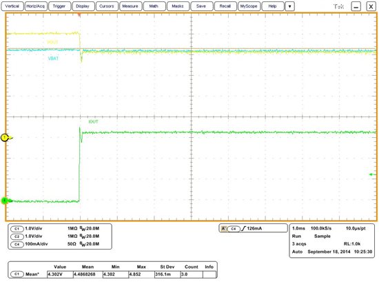
    Here is what I see on the scope.Yellow trace is VOUT, blue is VBAT, and green is IOUT

    Once I switched the load on, the output voltage drops to battery voltage, the battery is supplementing the load at this time.No oscillation showed up on our board. I do not know if the diode circuit you use to force CE pin will affect the output since we do not have this circuit on our EVM.

  • Jing,

    Thank you for the screen shot.  It is possible something is upsetting the BQ24032A, and I suspect something like that too.

    If you please refer to my schematic the idea was that  if USB or AC power was connected to the unit, Diode pair D7 could logically OR the voltage/currents, so that R69 and D9 create at 3.3V reference to CE from either USB or AC power.  I don't think this circuit is a problem.  It is possible that D10 may be causing problems, so what I will do is remove D10 so CE gets a full 3.3V.

    What is the status of your PSEL and CE pins? 

    In my case D9 would pull it up PSEL through a 100K (or 10K)  to 3.3V, also I see 2.7V at the BQ PSEL pin or the other side of R80  (i.e., on side of R80 is 3.3 the other is 2.7V).  I also made my microcontroller GPIO connected to PSEL an input to provide High impedance to PSEL input, and I observe 2.7V  That would say 60uA is being pulled through PSEL.  I expect 1 to 10uA.   Is this NORMAL?

    I didn't expect the PSEL pin loading the reference much.

    Another change I will make is to make the GPIO MCU pin connected to ISET2 (net CHG_100MAL_500MAH) an input.  I wonder if when the micro comes up causes issues at the pins.  I will make them inputs and try again. 

    In your setup you don't have a micro controller involved messing with the PSEL, and ISET2, so I suspect when I throw the switch ON, the Micro is setting up all its GPIO, something along the way causes imbalance on the BQ and messes it up.

    I will run some more tests.

    What should be the recommended ISET2 State (Low or High) before connecting USB to it?

    What is the recommended CE status before Power is applied to the Unit.  The voltage reference I created doesn't have much delay so 3.3V will almost reached at the same ramp rate as the PIN.  I don't believe there is a racing condition there.


    Rob

  • Both of the PSEL and CE are pulled high on our EVM. PSET is a HiZ input pin. It is strange that 60uA is pulled through PSEL. I did see this current on our board either.

    The input current limit is usually depending on user's preference. In your case, if you do not require the 100mA current limit at USB input, then you can probably just using the 500mA setting.

    For CE pin, it can be set to high before Power is applied.  

  • Jing,

    I have done everything to mitigate the issue and I just don't get it.  Removing the diodes doesn't do anything.  I don't know if it has to do with assembly issues.  I clearly hear an audible hissing or tone when the part oscillates.  I should also mention the 3.3V switcher is oscillating too so I am wondering if it is a transient condition or the 3.3V rail needs a supervisor to wait for the BQ to come up.

    If I set permanently ISET2 high, it just works.  In real life we will always be requesting 500mA to charge the battery from USB.  So I have to make sure this issue will not prevent a discharged battery from being charged from the USB. 

    I am out at a loss as to why this doesn't work with ISET2 low and battery.  Your load was not a switching regulator right?  You used a Resistive load or something right?  I wonder if the switcher inrush current is too high and causes the part to oscillate.

    I know the BQ has a mode to allow enumeration and then goes full current right?  What if during enumeration the Switcher is demanding current more than 100mA??

  • We do not have enumeration on our devices. At start-up, this device will be in USB 100mA rate for around 150 ms regardless of the ISET2 setting, then it will implement the CE and ISET2 inputs at the end of this time period. Do you see the oscillation at at start-up when you have ISET2 set high and load on? I am using a resistive load.  

  • Also, can you please confirm how is the battery voltage be measured. Is the probe connected at our IC side or on the battery side? Have you checked the input as well? Is it measured at IC input pins? 

  • The oscillations occur only when I throw the switch ON, and ISET2 is low.  Otherwise, if there is no load, the OUT pins are stable.  It will not oscillate

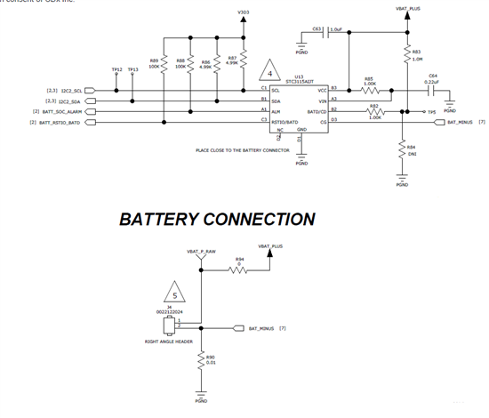
  • I am measuring the battery at the battery connector J4 PIN 1 (see my sch below).  I will measure it at the BQ pin.

    There is a power plane feeding the chip, so I don't expect it to be different but I will try.  The batter return goes through a 0.01ohms sense resistor for the fuel gauge.  That should not be causing problems.  this problem is bizzare! 

    Rob

  • I am stil unable to recreate the issue with wha we had at our lab. We probably would need to test with your board. Please contact me by email, so we can continue the discussion off the forum.

  • I removed Jing's email address from the post.  Hopefully you got it before I removed it. 

    Another question, how far away are the capacitors on the other side of the FET from the IC OUT pin.  Have you tried adding local bypass capacitance close to IC OUT and GND pins?

  • Jeff, Jing


    I got your email in time.  No problem.  If you please refer to my schematic, R79 = 0 ohms,  then SW2.  The switch is rated for 3A and so contact resistance is small.  The capacitors are about 250 mils away from the actual out pin.  I have about 57.1uF at that output, so that should be plenty bypassing at 250mils away.

    The picture below shows the out pins are routed in a shape to reduce inductance, and then it goes through R79 an 0805 0 ohms jumper which will be used to measure current later.  Then it goes to pin 2 of the switch, to pin 3 where the capacitors are located there.  Total distance is about 250 mils diagonal and about 350 mils Manhattan length.

    Again this is bizzare.  I wouldn't mind sending you a board and battery.  It just needs a standard 5.5mm jack wall wart or bench supply and you will see the issue.


    Rob