This thread has been locked.

If you have a related question, please click the "Ask a related question" button in the top right corner. The newly created question will be automatically linked to this question.

USB charging port of BQ24032A not working properly

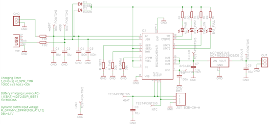
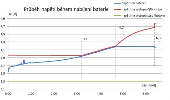
Hello I have board with schematics mentioned below. I'm using 2000mAh battery connected to bard and I'm charging the battery via USB or AC input. Via AC input the charging is done OK, but with charging via USB input not. Also the voltage on the output goeas above 4.4V I repeated measurement few times with the same result (AC charging is working, USB not). USB charging gives every time different results, but every time it does not charge correctly (also battery full does not lit up). Can someone help me with it?

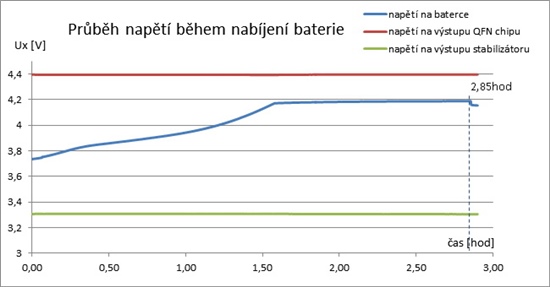
AC input charging

red: output of BQ chip

blue: battery voltage

green 3.3V board output

USB charging input

  • When power is applied via the USB pin, the input voltage is switched straight through to the OUT pin, unless the USB input current limit is active, and then the OUT pin voltage will typically drop to the DPPM-OUT threshold or Battery voltage (which ever is higher).  The input current limit is either 100mA or 500mA, depending on the state of ISET2; therefore, the charge current will be clamped to the ISET2 setting, regardless of the charge current setting per the ISET1 resistor.

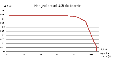
  • Ok, as I understand from reply, if AC input is connected to power supply, the BQ output is regulated to 4.4V (in my case), if USB input is choozen, the output voltage of BQ is limited to USB port voltage? I made also current measurement and the second problem I mentioned is battery full led. If charging via USB (500mA), then after BQ goes to constant voltage mode and current is below 9,8mA, the LED still does not lit up. If I use AC input for charging (current 1A), the LED lit up. below is chart of USB charging (y axis current, x axis charged capacity). As I know effeciency of charging is not 100% so the battery capacity counted from current is higher than expected.

  • To your first question, yes, in USB mode, the USB voltage is passed through to OUT. 

    To the second question, if any of the other control loops (DDPM, input current limit, thermal) are active instead of only the constant voltage control loop, the IC disables termination. 

  • I measure also battery and BQ chip temperature. The temperature on battery did not go over 24°C (room temperature 22°C), the chip tempereture did not go over 40°C. If I look on the charging current on the beginnig of charging cycle, there is constant current so I expect, that DPPM is not running. On the end of charging cycle, the current is less than 9,8mA and USB can supply more power so it should be ok. The tepmerature is acceptable also. The output of BQ chip supplies only 3.3V linear regulator, nothing is connected to the output of 3.3V regulator.

    I will make few more measurements and will make measurement of input voltage also.

  • Hello I made new measurements with new PCB and new BQ chip. The trouble was in the malfunctioning USB input on the previous PCB. I made excactly same measurement on the new PCB with same component values and the finishing of charging cycle now works without problems. When I replaced BQ chip on the previous pcb, the charging cycle on the USB port works also OK (led "battery full" lit up). Thank you very much for support and clearing the informations about BQ chip functions.