This thread has been locked.

If you have a related question, please click the "Ask a related question" button in the top right corner. The newly created question will be automatically linked to this question.

BQ24610 AC Detection

Other Parts Discussed in Thread: BQ24610

We are using the BQ24610, and are using a design based on the reference design in the data sheet, after choosing our currents and voltages and such.

We are having two problems:

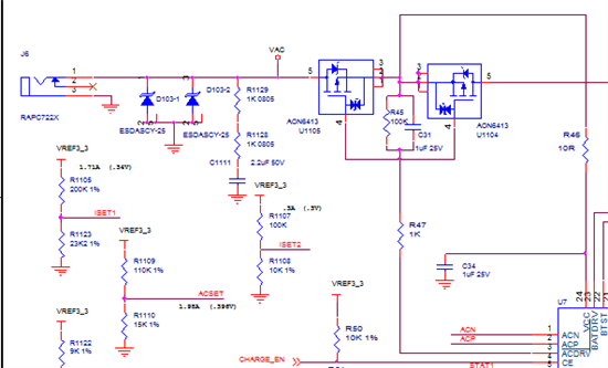
1) The BQ can detect when the charger is plugged in and will assert STAT1 appropriately.  It however will not detect that the AC has been removed.  When we look at the gave voltage of the ACFET combination, it drops the better part of 6 V, but not the full 6V the datasheet says.  We are using the 100K across the G/S with the recommended capacitor, with a 1K to the ACDRV pin on the part.  It seems in capable of shutting the FET off, like it is latching up.  The part seems to think it is charging the battery from the battery (STAT1 stays asserted). If we then ground the gate of ACFET momentarily, then it shuts off as expected.

2)  After having charged successfully once, I can no longer charge any cells.  I see the HIDRV and LODRV strobing appropriately, but it is just not drawing any current.

Thanks for any help.

  • Hi Colin,

    1) Could you share the schematic that illustrates the connections you described for this problem in your post? Are you using the TI EVM for this device or have you created a PCB for evaluating this device? The ACDRV pin is designed to drive P-channel MOSFETs, but what you are describing sounds more like N-channel MOSFETs tied to the ACDRV pin.

    2) It sounds like the device hasn't reached the recharge threshold. The voltage must drop 50mV (with respect to the feedback voltage) on the VFB before the device will begin a recharge cycle. All conditions for initiating a charge cycle must also be met for a recharge cycle.

  • 1) Please see attached.  We are using P-channel mosfets (AON6413), back to back in the same configuration as in the reference design.  There is also a 10K resistor from VAC to GND which is not shown, which doesn't seem to be draining it the voltage at the jack when we pull it out.  We created out own PCB, on a larger form factor for ease of layout and testing, than the final target board.  If we regulate the voltage down with a bench supply, then it does shut off, but not if we just pull the plug.

    2) STAT1 is indicating that it is charging.  Is this sufficient to determine that all the conditions have been met?  Just no current is getting through.

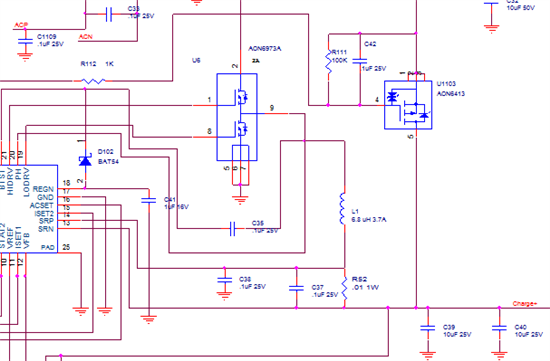
    3)  If we probe the PH and LODRV lines, they have identical waveforms, the one shown for PH in figure 8 in the datasheet.  We are using a AO6973A as the transistor set for this. (Has high and low side in one package)

  • 1) What is your nominal VAC voltage? When you pull the plug, what is the voltage on VAC and VCC? VCC must be below 4.1V (typical value) before the IC sees this as an UVLO event. ACDRV and BATFET are disengaged when VCC <= 4.1V. So from this, it sounds like the UVLO threshold is not being reached, which is why the ACFETs are still conducting.

    2) What is the regulation voltage set to (final battery voltage)? How many cells in series are being charged? If STAT1 is low (indicating "on") and STAT2 is high (indicating "off"), then all conditions for charging have been met. Does the battery voltage drop down to the recharge threshold when you are expecting a recharge to occur?

    3) PH and LODRV signals should not be identical since it sounds like the IC is operating in non-synchronous mode. While the PH waveform can look like that of figure 8, the LODRV signal should be like that of figure 7 and/or 8. LODRV signal should be clean. It's possible that there is a layout/coupling issue here. During synchronous operation (when charge current >0.5A for your application), then the waveforms should look like figure 6.

  • Thanks for your response.  I was pulled away to work on another project and didn't get back to this until now.

    1) We are supplying 18-20 Volts.  Pack voltage fully charged is a nominal 16.8 with 4 cells. This problem of not detecting absence of VAC seems to have gone away during the two months it sat on my bench.  I'll keep an eye for it repeating.

    2) The final pack voltage is set to 16.8.  We are seeing STAT1 being asserted as charging.  We are plugging in partially-discharged cells giving us a VFB on pin 12 of about 1.8V .  It says it is charging, but just not drawing any current.  The ISET1 is set to 750mA, and ISET2 is set to .3A. and ACSET is set to 1.98A

    3) I should have said that PH and HIDRV are identical.  It's like PH is looping back through BTST into the HIDRV pin.  As before, the BQ indicates it is charging, and drawing no current.  LODRV looks normal like in figure 8, and that's what PH looks like too, which would indicate it thinks it needs a 100% duty cycle.  But no current is going through.  Figure 8 doesn't indicate what HIDRV should look like.

    4) We are seeing -0.200 mV across the SRP-SRN current sense resistor.

    So at this point

  • Colin,

    When you say PH and HIDRV are identical, does this mean the switching converter is not switching at all? Is PH a DC voltage or do you see pulses? Could you list the voltages for each pin in your setup?

    Also, if your reading of -0.2mV is accurate, that is implying that current is coming out of the battery.