This thread has been locked.

If you have a related question, please click the "Ask a related question" button in the top right corner. The newly created question will be automatically linked to this question.

BQ24610 - Blinking STAT1 - Abnormal charge termination

Other Parts Discussed in Thread: BQ24610

Hi,

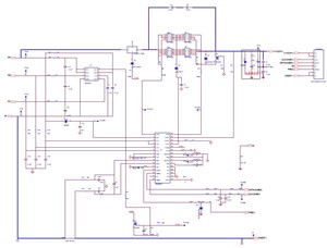
3603.Schematic Prints.pdf
I designed a battery charger for a 3S2P Li-Ion battery pack. The battery charges correctly from 4% to 100% but at the end of the charge, STAT1 starts to blink and STAT2 never turns on.


Could you please help ?

I have attached my schematic.

DC_IN= 19V

ID =GND when battery is plugged.

Measured charge current (fast charge)=2.04 A

Measured charge voltage (fast charge)=12.6V

Thank you.

  • Hello,

    can anyone help with this issue ? Do you see anything wrong in the schematic ?

    My battery pack specifications are:

    (1) End of charge current

    Taper current < 220mA

    (2) Charge voltage

    -          12.6 +- 0.12V

    (3) Charge current

    -          Battery voltage < 9V ,  300mA

    -          Battery voltage >= 9V, 2200mA

    Fully charged condition need to meet the below conditions:

    pack voltage >=12.3V

    Taper current <220mA

    Are my settings ok or should I change something ?

    Thanks.

  • Hi,

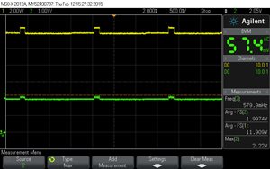
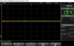
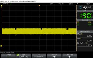
    I did attach the scope showing VBAT (PACK+ on the schematic) in yellow and VFB in green.

    This happens when the charge is complete.

    Any idea on what could make this happen ?

    Thank you.

  • Hi,

    after more investigations, it seems that the battery never reaches its full charge voltage, ie 12.3V. Charge current drops to 0 when it reaches approximately 210~200mA.
    Battery pack voltage is measured at 11.95 to 12.15V (depending on the battery pack). This makes VFB falls and the charger try to restart the charge cycle. I think that's whay STAT1 blinks.

    So now my question is why does the battery voltage stay under 12.3V when it is fully charged.
    I bypassed the dividers on ISET1 and ISET2 by connecting power sources on the BQ24610 (VISET1=0.6V ; VISET2=0.3V) but I didnt had better results. I also changed the resistors on VFB to set VBAT=12.7V but once again, the battery pack only charges to <12.3V.
    Any idea to help ?
    How can I change VRECH ?

    Thank you.
  • This phenomenon is the battery detection scheme (see figure 19 on page 22 of the datasheet) that is triggered during power on reset or when recharge is triggered (Vfb < Vrech). It looks like the the battery detection scheme passes the first test which is to sink 8mA from the battery for 1s and check to see that Vfb is not lower than Vlowv (which is 1.55V on FB pin). Because this test passes, the charger starts charging the battery, and the battery voltage immediately jumps up to ~12.6V (estimating from the scope capture). When it reaches 12.6V, the charger stops charging the battery. However, it looks like as soon as the charger stops charging the battery, the battery voltage drops (>50mV drop on Vfb) causing the charger to go into a new recharge cycle. This indicates that the battery pack is not allowed to charge, but discharge is allowed (since the charger is able to draw 8mA from the battery during the battery detection scheme). 

    Could you capture the waveform at the PH node? It should start switching as soon a battery is detected. Also, do you have the charge voltage and current profile of the battery pack as it nears 12.6V?

  • VRECH threshold is a fixed value for a given charge voltage target set by the resistor divider on the FB pin. It is indicated by FB pin voltage dropping by 50mV.
  • Hi Smriti,

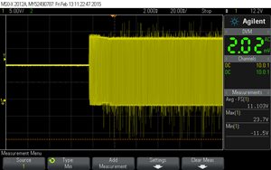
    Here is the scope of PH when battery starts to charge:

    During fast charge voltage phase, I can see the battery current drops from ~1.95A to ~200mA then falls to 0.

    At the end of charge, battery voltage is between 11.95 and 12.15V.

    This voltage seems to be normal as the BQ30z554 inside my battery pack will close the 2x charging MOS when the battery is fully charged (ie 12.4V on the BQ30z554). When the 2x charging MOS are closed, the voltage will decline about 0.3~0.5V because body diodes are on.

    Now my problem is that I need to set the charging voltage to 12.6V but I need the BQ24610 to consider that my battery is fully charged when VBAT=11.95V.

    I wonder if the BQ24610 is the correct charger to use with my battery pack...

  • Selim,

    I"m a little confused. You would like to set the charger to 11.95V as the target instead of >=12.3V?

    You mentioned that the BQ30Z554 opens the back-to-back N-channel MOSFETs when the battery charges to 12.4V. Are you saying the charger charges the battery to the correct voltage of 12.4V the first time around, but does not charge to 12.4V during a recharge?

  • When the cells are charged to >12.3V (battery fully charged), the voltage on the battery pack connector is 11.95~12.15V.
    That's why the charger (BQ24610) will only see 11.95V~12.15V when the battery is fully charged. So I think that the target should be 11.95V instead of >12.3V. Am I missing something or is this hypothesis seems correct ?
  • Selim,

    If the pack is being charged to 12.3V, then the voltage after charge termination should be ~12.3V (there might be a slight droop, but not all the way down to 11.95V-12.15V). There are several reasons why the charge terminated voltage can be lower than the charging voltage:
    1. The charge FET is not on. This could be due to several reasons, depending upon the settings on the gauge inside the pack.
    2. The charging current is too high which results in reaching the termination voltage earlier (due to battery internal resistance, battery heating, etc.), causing the charger to terminate prematurely. And since the charger terminated prematurely, the battery has not reach max capacity. This will cause the cell "relaxed" voltage to come down significantly quickly (because it's not fully charged).

    In either case, I recommend reading the settings of the bq30z554 from the pack or getting the pack manufacturer's help in reading the settings. The register read back from the bq30z554 could explain why the terminated voltage is lower than the charge voltage.

    In any event, the charger voltage should be set to what you need to charge the batter to (>12.3V in this case). So that charger is configured correctly. If everything is behaving normally (both the charger and gauge working correctly), the voltage on the SRN pin of the charger could be higher at high charging current or could be equal to the voltage on the pack terminals at low currents.
  • Hi Smriti,


    I changed VISET1 to 0.3V for 1.5A charge current. I will do a complete charge from 5% to 100% to check if the problem is due to a too high charge current or not.

    Thanks.

  • Hi Smriti,


    charging with VISET1=0.3V didn't change anything, the charger always tries to restart the charge when battery is full...

    Something I've noticed is that charge current is always less than what it should be, ie with 0.3V from power supply on VISET1, max charge current is near 1A during fastcharge current regulation phase when it should be 1.5A.

    Any idea ? Can it be a noise issue as my schematic is almost the same as the typical schematic ?

    thanks

  • Smriti,

    Please find here my battery pack protection circuit schematic

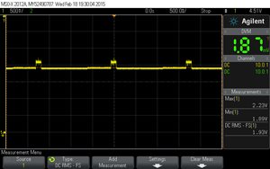
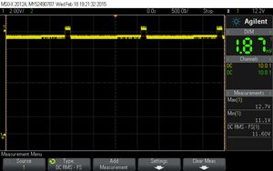
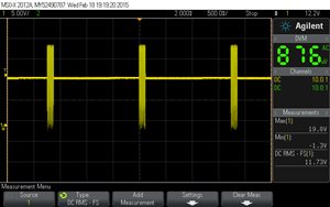
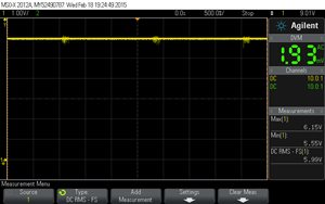
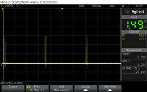
    These are different scopes when the charge is complete but STAT1 is flashing.

    VFB:

    SRN:

    PH:

    REGN:

    LODRV:

    TS:

    TTC:

    I did try to set VBAT to 12.3V and VISET2 to 0.17V but in that case the battery charged to 95% then STAT1 started to flash (VBAT was 11.6V).

    Is there anything else I can do to debug this board ?

    Thanks

  • Selim,

    Replace the battery pack with a voltage source that can sink current. This voltage source will act as your battery simulator. Increase the voltage source from the minimum battery voltage to the maximum battery voltage that the bq24610 is configured for. If the battery charger acts as suspected as you traverse the span of the battery voltage range, then we might be able to narrow it down to the battery pack.