This thread has been locked.

If you have a related question, please click the "Ask a related question" button in the top right corner. The newly created question will be automatically linked to this question.

BQ25895 SYS output on USB power

Other Parts Discussed in Thread: BQ25895, TPS61200

We are using the BQ25895 and have an issue I can't figure out. When powered from VBAT (no VBUS plugged in) the output on SYS is great (4.2V) and the system is drawing 40ma of current. Then I power the device with VBUS only (NO VBAT hooked up) the SYS output switches off and on. In other words it won't maintain output. If I remove the load, there is voltage at SYS consistently with no cycling. It seems to be a current limit problem, but is so little current being drawn, it doesn't make sense. I'm using the standard schematic from the reference design below.

Project Title: USB-C DFP + 5V2A Power Bank With Input Fast Charger Reference Design

I have I2C communications available if I need to change something, but I thought this chip should operate standalone? Do I need to set a seeting on the chip? I have ILIM at 260 ohm as directed in the reference design. 

What am I missing?

  • Could it be that the BQ25895 will only operate when there's a battery hooked up?
  • The charger has an input current limit feature.  At startup, input current is set by the D+/D- communication with the USB power source.  If determined to be an SDP port, the input current limit is only 500mA.  If determined to be DCP, the input current limit is determined to be the lower of the value set by ILIM (assuming the EN_LIM register bit is set) or 3.25A.

  • Thanks for the reply Jeff.

    I did read that in the manual, but we are only drawing 200ma at the peak, so I'm not sure how that can be the issue. Also, as I mentioned, when I hook up a battery, everything works fine and the USB is drawing current without issue.

    I have three prototypes all demonstrating the same behaviour. 

  • When battery is attached, the battery supplements the system load through the battery FET that connects BAT to SYS. The charger also has the VINDPM feature which monitors the voltage at VBUS and reduces the input current limit if the voltage sensed at VBUS drops below the VINDPM threshold. By default, VINDPM is set to 600mV below the voltage at startup when the charger is not loaded. Is it possible that your connection to the input source is highly resistive, causing a voltage droop at VBUS pin that triggers VINDPM? What is the voltage at VBUS pin when this happens?
  • WOW you are very smart!

    In fact, I didn't say that I had added a switch rectifier between the USB voltage pin and the input of the chip, which is adding resistance. It was a feeble attempt to inject solar power into the charger, when there was no USB present. I have the solar input voltage set at 4.5v so when the USB would be plugged in, the rectifier would choose the higher voltage (USB). As you said, its also contributing to a voltage drop on the USB! So I just bypassed the switch and it is certainly behaving differently. Need some more time to do some testing.

    Any guidance on how I can inject solar into the charger, so I don't screw up the functions of the chip? I couldn't find anything in the reference design area... Help would be greatly appreciated!

    Thanks again!!!!! John
  • I should also say the solar is using the TI reference design with a TPS61200 and the additional MPP tracking circuit
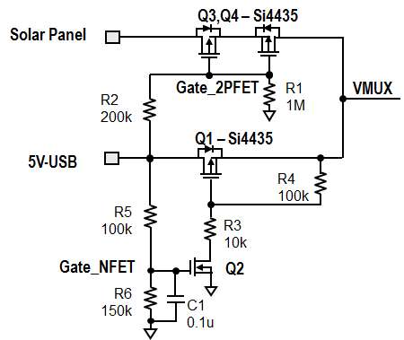
  • Instead of diode OR/rectifier, you might want to use back to back PFETs for lower voltage drop. Two FET are necessary due to the body diodes of each FET. I assume you are boosting the solar panel to 5V using the TPS61200? How much current are you getting from the TPS61200?
  • Appreciate your time, especially on a weekend! Seriously

    Yes, its only a 4w panel, so max current @5v ~800ma at full sun, which it rarely will see. Its always connected and the plan is to keep the system alive by harvesting energy whenever the sun comes up. Here is the example I based the attempt on, but I used a higher current device..

    I have R1 calc'd to keep the voltage below the 5v USB so when you plug in the USB, it will select that source. We were trying to keep it simplet.

  • That didn't post quite right. Here's the solar diagram I used.

  •  When both the USB and solar panel are connected, if you want to get any power from the panel, the voltage at the output of the TPS61200 needs to be set higher than the USB voltage.  The max output current you will get from the panel through the TPS61200 can be estimated using a power balance:  efficiency = Vo/Io / (Vmpp*Ipanel).  To minimize losses through diodes, I recommend the attached circuit or something similar instead of diodes to create the MUX. I also recommend that you dynamically change the input current limit and/or use the charger's ICO feature to optimize the input current limit, especially when only the solar panel is connected.  You will also need to manually change the VINDPM threshold.

  • AMAZING JEFF! Thanks again and I will do just that! Consider me a very happy customer!

    Perhaps TI should consider making this circuit into an actual device? It seems to me that the need for switching between USB/wireless/Solar charging is an important trend and having a totally integrated device can only serve to accelerate TI adoption. Or add a second input to the BQ would be great. :)

    Best! John

  • I was applying the circuit today and noticed that there wasn't a part number called out for the GAte_NFET. I don't want to screw up again and wonder if you can recommend a part number?

    Thanks! John

  • the NFET can be any low cost NFET with Vth <=3.0V. 2N7000 should work.