This thread has been locked.

If you have a related question, please click the "Ask a related question" button in the top right corner. The newly created question will be automatically linked to this question.

BQ24133: basic questions when I see the BQ24133 datasheet..

Part Number: BQ24133
Other Parts Discussed in Thread: , BQ24172

Hi,

I am beginner for battery charger, and willing to use TI's BQ24133.

Now I'm reviewing BQ24133 datasheet, and have several quesitons as below.

1. Typical Application Schematic at page 1 of BQ24133 datasheet.

-> There are 3 P-channel FETs as Q1, Q2, and Q3. I wonder what the role of these compenents is.

-> I'd like to know why Q1,Q2 two compenents needed at the input. Also I'm very curious if I can use just diode rather than Q3 at BATDRV pin.

2. Table 3. STAT Pin Definition at page 23 of BQ24133 datasheet.

-> I found LED blinking at abnormal status, and also found the blinking time period is different from various abnormal status.

-> Can you explain the rule of STAT LED blink period?

3. 10.2 Typical Application at page 25 of BQ24133 datasheet.

-> VBAT is connected to AVCC input. Is there any special reason?

4. I found the switching period is random at normal operation.

-> I cannnot found any explanation of this random switching period. Is this the normal behavior expected by TI?

Please review above questions, and give answer for me.

Thanks,

TS

  • Hi TS,

    Glad you found bq24133 as potential to your application. To answer your questions:
    1. Q1 serves as input inrush current control. This FET slowly turns on to limit the current going into the converter during start up. Q2 serves as reverse blocking FET, which prevents any current from going back to the input if there is no adapter present. You can replace BATDRV with diode.
    2. What are the conditions when the STAT blink frequency looks different? From the datasheet, it should blink at 0.5Hz.
    3. You don't need to connect VBAT to AVCC.
    4. Can you send a waveform of this random switching period? Is this on a design you made?

    Regards,
    Steven
  • Hi Steven,

    Thanks for your kind answer.

    Below is my schematic, and can you review for me whether there's any problem?

    Actually my boss draw this schematic, but I have to follow up everything from now on.

    SCHEMATIC1 _ 2.pdf

    And one more question.

    I tested with TI's evaluation board called " BQ24133EVM-715-5V ".

    And I found the charging status is different as per input voltage level.

    1. Vin : 8.9V

    -> when the battery voltage is up to 8.1V, then continue charging with under 50mA.

    2. Vin : 9.1V

    -> charging normally complete at 8.4V. Just after finished charging, the detached battery's voltage is over 8.35V.

    I wonder the reason why the charging status is different due to input voltage.

    Thanks,

    TS

  • Hi TS,

    I want to make a correction to my previous post just in case someone else is reading this. You will need to connect VBAT to AVCC using the diode OR connection if you have a MOSFET at BATDRV as the logic to control this gate is biased by AVCC. But because BATDRV is replaced with a diode in this application, then VBAT does not have to be connected to AVCC.

    Here are a few things for your schematic:
    1. Remove R23, Q3 and Q4 and replace with diode if preferred, if not, then VBAT has to be connected to AVCC with diode OR connection. Also, only Q4 is needed.
    2. Remove D4, because Q2 is there for the same reason, plus you get inrush control with Q1
    3. Change L2 to 6.8uH, charge current is lower than 1A
    4. Remove CT10, no need for this cap when lower than 1A charging (only need 10uF output cap)
    5. Some of the caps are big in size, is this due to BOM limitations? I think using 0805, 1206 or 1210 size is good enough for all the ceramic caps 0.1uF < C <= 10uF, and 0603 for C <= 0.1uF.
    6. R24 and R26 can both be 1206 as well, just like R16 and R17
    7. Place 0.047uF and 499kohm in parallel with gate and source of Q1 + Q2 (look at EVM schematic), this helps with inrush current control
    8. If you want reverse input protection, you can also look at Q1 of our EVM schematic
    9. I suggest adding 2ohm + 2.2uF RC filter at the input (look at R4, R5, C3 of EVM schematic). This helps with input hot plug overshoot. Be sure that resistors are 1206 size at least (to handle power spike for t<10us)
    10. Pull up STAT to V_EXT instead of VREF, adjust R31 accordingly
    11. In the layout, make sure that ACP and ACN are connected directly to the input sense resistor with a kelvin connection, same thing with SRP and SRN with charging sense resistor.
    12. Place 0.1uF to ACP close to the IC pin. Make sure C7, C11 and C13 are placed close to IC pins as well.
    13. Place a 330pF 0603 cap in parallel to R25 close to the IC. This filters any sudden input voltage movement and prevents false triggers on OVPSET.
    14. Use ceramic capacitors for this application (except for CT6, CT7 and CT8), as ceramics have less ESR which is good for DCDC converter performance.

    The reason you are seeing the changes between input voltages is because of duty cycle limitations. When you are near 95% duty cycle, the bq24133 starts to pulse skip and loses regulation. You need to maintain input voltage higher than 95% duty cycle from max battery voltage so that you don't lose regulation. Your input voltage must be higher than VBAT/.95 + IR drop.

    Regards,
    Steven
  • Hi steven,

    thanks for your previous review and answers.

    It was very helpful for our design activities and also for my personal study.

    I have several additional questions as below.

    (if it need another separate new E2E thread, please let me know.)

    1. I'd like to know the re-charging condiotion.

    If I set as below table, then the full charge is at 0.073A? (If the voltage is 8.4V?)

    ITERM

    ITEM

    0.07318548

    A

    magnification


    200


    Reference Voltage

    VREF

    3.3

    V

    Sensing Registor

    RSR

    0.01

    ISET pin voltage

    VISET

    0.146370968

    V

    ISET Pin resistor

    R29

    237

    KΩ

    ISET Pin resistor

    R34

    11

    KΩ

    2. When is the re-charging start after below sequence

    connect charger / turn on the terminal -> complete charging -> terminal operate -> when re-charging start ?

    (re-charging do not work when the battery voltage is under 8.2V)

    The above condition is that terminal operate after connect the charger, and the load current is high so pulled the battery current as well as the charger current.

    After operate about 3 hours, the battery voltage is under 8.2V, but the re-charging do not work.

    is there any special condition needed for re-charging?

    I found the below table at datasheet, and I understood that the re-charging start when the voltage is lower about 0.14~0.26V from 8.4V. Am I right?

    3. the classification of Precharge and fast-charge

    3.1. If I set the fast charge timer, then the precharge do not operate?

    3.2. If I connect the 100nF cap to TTC port, then the calculation result is 540 minutes. This mean that the fast charge operate in this time periods?

    - I do not fully understand about the TTC timer operations, but when I set the about 11nF 60minutes time, then the battery fully-charged about 150minutes after.

    Below is summary of my questions.

    #. I'd like to know the recharging condition when the charger is connected.

    - battery 8.26~8.14V recharge start status

    - the condition for TTC or precharge timer operates.

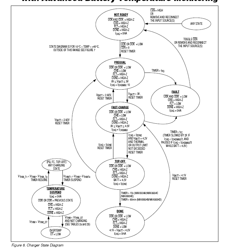
    finally, If TI have flow chart such as below (MAX8934) attached?

    thanks,

    TS

  • Hi TI,
    I'm still wating your answer.
    If my question is not clear enough for answer or need more time to reply then please let me know.
    thanks,
    TS
  • Hi TS,

    1. Yes the termination current is about 0.073A, When the charge current lower than 0.073A and not in INlimit, BQ24133 will terminate the charging.
    2. Recharge when the battery charges to full then VBAT drops to about 8.2V(Consider the error, please try to discharge the battery to 8V), BQ24133 will start to re-charge.
    3.1 No, pre-charge has a independent 30mins safety timer.
    3.2 Yes, Tchg=CTTC*KTTC. but the time range is 1~10hours. Please try to set TTC to a couple hours.

    Alen Chen
  • Hi Alen,

    thanks for your answer.

    I'd like to ask several things from your reply if possible.

    2. Recharge when the battery charges to full then VBAT drops to about 8.2V(Consider the error, please try to discharge the battery to 8V), BQ24133 will start to re-charge.

    -> for this, I attached a table from the BQ24133 datasheet. You mean I can refer to the table? As for my test result, the recharge work at 8.31~8.32V.

    The purpose of this question is to prevent the frequent recharge when the customer use the terminal with connecting the charger.

    3.1 No, pre-charge has a independent 30mins safety timer.

    -> I understand that the pre-chare is the function that charing about 1/10 of fast charge.

    I'd like to know the 30minutes timer operate condition for this charge mode.

    If set the charge as 700mA, then pre-charge is 70mA. this mean the complete charge currnet. then charge finished, and pre-chare doesn't need the timer.

    Am I right?

    3.2 Yes, Tchg=CTTC*KTTC. but the time range is 1~10hours. Please try to set TTC to a couple hours.

    -> I'm okay for the timer setting.

    So the timer means the maximum cc-mode charge time ?

    Regards,
    TS

  • Hi TS

    2. Recharge when the battery charges to full then VBAT drops to about 8.2V(Consider the error, please try to discharge the battery to 8V), BQ24133 will start to re-charge.

    -> for this, I attached a table from the BQ24133 datasheet. You mean I can refer to the table? As for my test result, the recharge work at 8.31~8.32V.

    The purpose of this question is to prevent the frequent recharge when the customer use the terminal with connecting the charger.

    --> Which table?  How about you battery's internal resistance? Can you provide your battery's technical document.

    3.1 No, pre-charge has a independent 30mins safety timer.

    -> I understand that the pre-chare is the function that charing about 1/10 of fast charge.

    I'd like to know the 30minutes timer operate condition for this charge mode.

    If set the charge as 700mA, then pre-charge is 70mA. this mean the complete charge currnet. then charge finished, and pre-chare doesn't need the timer.

    Am I right?

    --> Pre-charge means your battery excessive discharge typically Vbat is lower than 3V per cell.

    3.2 Yes, Tchg=CTTC*KTTC. but the time range is 1~10hours. Please try to set TTC to a couple hours.

    -> I'm okay for the timer setting.

    So the timer means the maximum cc-mode charge time ?

    --> No CC-mode and CV mode.

    Alen Chen

  • Hi Alen,

    thanks for your answer.

    I needed some time for prepare materials you request.

    2. --> Which table?  How about you battery's internal resistance? Can you provide your battery's technical document.

    you can find the table from datasheet at previous thread ( Mar 15, 2017 6:23 AM ),but I re-attached as below.

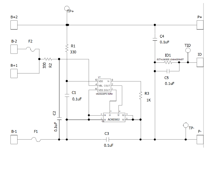
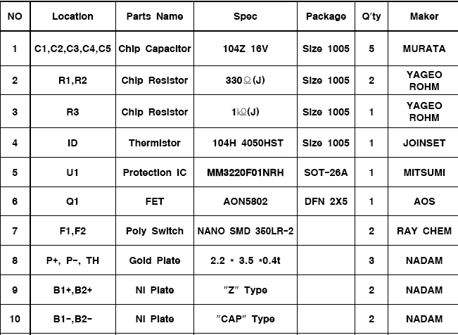
    and also below is PCM circuit and PCM Part list.

    3-1. --> Pre-charge means your battery excessive discharge typically Vbat is lower than 3V per cell.

    I'm sorry but I cannot understand what this function is.

    Please explain more details or you can share the TI documents about this.

    New question >

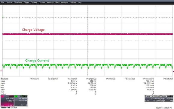
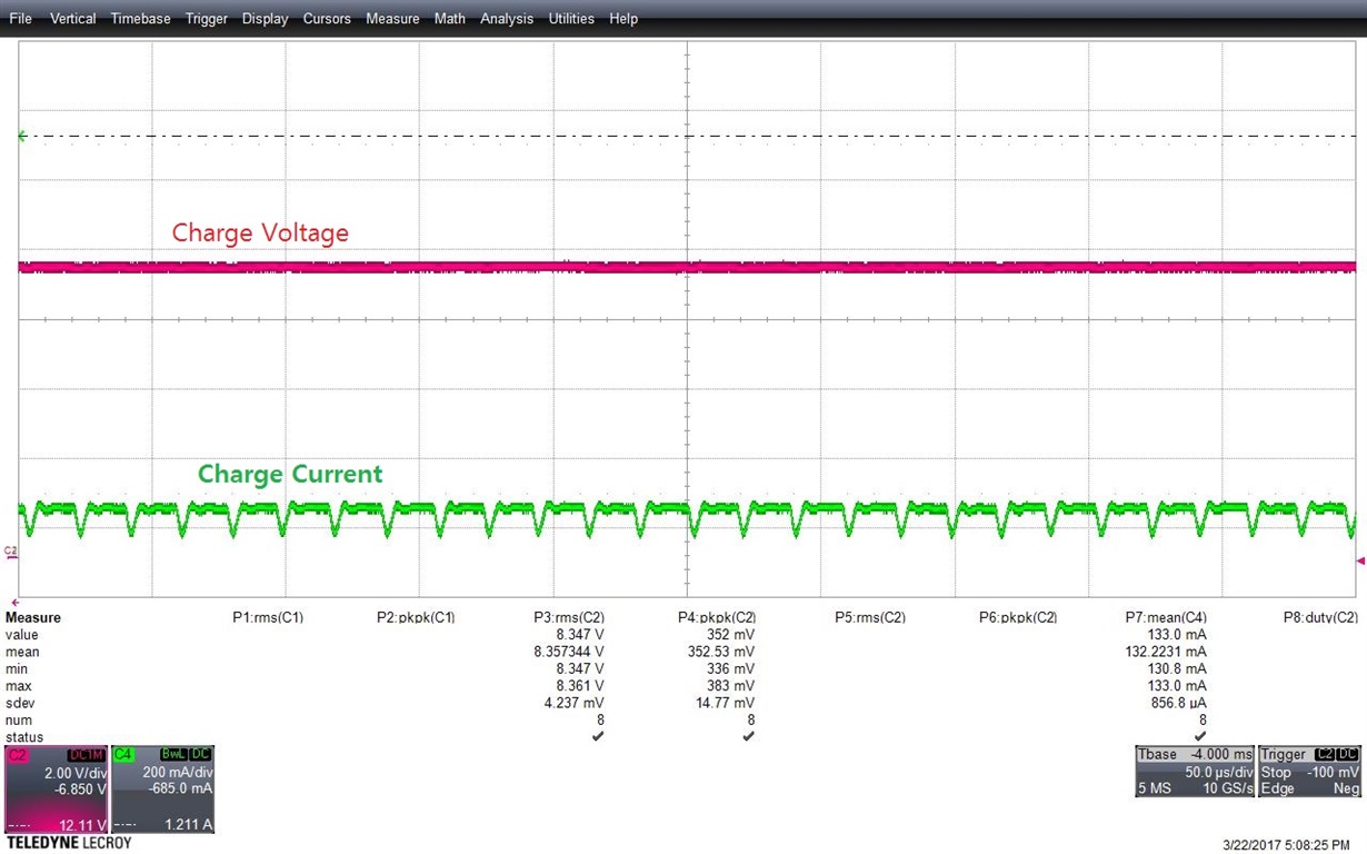
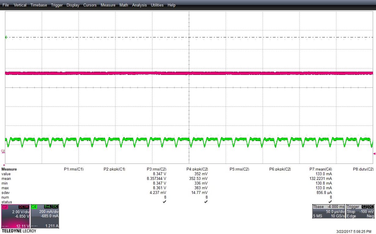
    Below waveform is from charging as 110mA. (Current Probe).

    I can see below waveform when the chaging current is low.

    charging voltage is 8.347V.

    Regards,

    TS

  • In addition,
    this project is almost finish step, so I need to determine as soon as possible.
    Please reply promptly.
  • Hi TS,

    3.1  Please refer the charge profile below

    I can't see the time scale in the picture, can you upload a high resolution one?

    Alen Chen

  • Hi Alen,

    3.1  Please refer the charge profile below

    -> I already found that chart. However, my question is the explanation for numerical factor of Pre charge time (of timer) and fast charge timer function of action.

    According to my test, when charging the fully-discharged battery, there is almost no pre charge time and just switch over the cc mode.

    I'd like to know the independent 30mins safety timer of pre charge and also other functions of pre charge.

    3. please review below original waveforms.

    <CV mode current>

    <NO9-CHARGE (BAT AHN2)>

    4. Additional Question.

    Below waveform is from the battery manufacturer.

    (I had problem for charging, so requested analysis to battery manufacturer and got below waveform from them.)

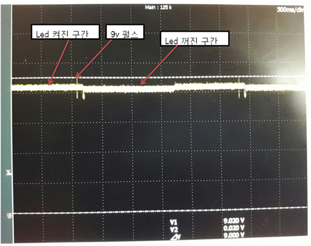
    As below waveform, when connect the battery to charger, 9V overshoot occurs and battery PCM module shut off the charging. And repeat same operation continuously.

    (battery charge status is under 50%).

    Can I ask which one is the root cause, battery or charger ?

    Regards,

    TS

  • Hi TS,

    3.1 Generally, the time of pre-charge is very short because of the capacitance on Vbat<3V is very small and meanwhile the internal resistance of the battery is big , If you want test pre-charge you need to clamp VBAT lower 3V/ per Cell. You can use electronic load to clamp VBAT.

    3. Please plot IL(inductor current), PVCC, VBAT, ICHG. Can you provide the schematic and Layout?
    4. I can't judge, can you please try to test other battery pack?

    Alen Chen
  • Hellow Alen,

    3.1 Generally, the time of pre-charge is very short because of the capacitance on Vbat<3V is very small and meanwhile the internal resistance of the battery is big , If you want test pre-charge you need to clamp VBAT lower 3V/ per Cell. You can use electronic load to clamp VBAT.

    -> I understood. Thanks.


    3. Please plot IL(inductor current), PVCC, VBAT, ICHG. Can you provide the schematic and Layout?
    -> I attached final schematic as below.

    SCHEMATIC1 _ 3.pdf


    4. I can't judge, can you please try to test other battery pack?

    -> I found there's no problem with anorher battery pack. Though this is battery problem, can you explain the cause of this symptom?

    5. Additional question.
    I tested the unit which BQ24133 is applied, from -10'c to +50'c temperature with chamber.
    There was no problem at low temp, but at +50'c charging LED is blinking. (with charger connected status)
    Q1. Blink operate wien THM works?
    Q2. After THM works, the temp back to room temp then charge should be back to normal, isn't it?

    TS

  • Hi TS,

    3.1 It means very few capacity in VBAT lower than 3V. So you can't see easily.
    4. I can't find the waveform. Why do you add R143, R145?
    5.Q1: What does THM mean?
  • Q2: BQ24133 seems temperature would be to high. Please measure the voltage on TS pin.
  • Hellow Alen,

    Please plot IL(inductor current), PVCC, VBAT, ICHG. Can you provide the schematic and Layout?

    -> How should IL measure be taken?

    -> ICHG means, do you want charging current?

    I can't find the waveform. Why do you add R143, R145?

    -> Battery OVP operates because the 'Cut-off voltage of battery' and 'a margin of error of full charge voltage of charger' is wrapped over.

    -> So the battery does not full-charged, so R143, R145 is added for reduce voltage.

    -> Is there any other solution to lower charging voltage?

    #. ovp voltage of battery 8.450V - tolerance 0.020V = 8.43V

    #. full charge voltage of charger 8.4V + tolerance 0.5% = 8.442V

    I can't judge, can you please try to test other battery pack?

    -> As I said, I found there's no problem with anorher battery pack.

    -> Though this is battery problem, would you please give me any help about this symptom?

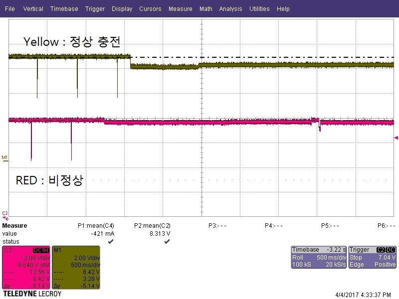
    -> Below is the waveform that compare the normal charge(Yellow) and abnormal one(Red).

    TS

  • Hi TS

    Please plot IL(inductor current), PVCC, VBAT, ICHG. Can you provide the schematic and Layout?

    -> How should IL measure be taken?

    [Alen]: please refer to the picture below

    -> ICHG means, do you want charging current?

    Yes, Charging current

    I can't find the waveform. Why do you add R143, R145?

    -> Battery OVP operates because the 'Cut-off voltage of battery' and 'a margin of error of full charge voltage of charger' is wrapped over.

    -> So the battery does not full-charged, so R143, R145 is added for reduce voltage.

    -> Is there any other solution to lower charging voltage?

    #. ovp voltage of battery 8.450V - tolerance 0.020V = 8.43V

    #. full charge voltage of charger 8.4V + tolerance 0.5% = 8.442V

    [Alen]: Two method: 1. Using BQ24172 witch has FB pin. Can adjust charge voltage.

    2. Typically, a 8.4V battery has a 8.7V OVP voltage. you can adjust the voltage of OVP. R143 and R145 have not much effect  because the charge current is very low before fully.

    I can't judge, can you please try to test other battery pack?

    -> As I said, I found there's no problem with anorher battery pack.

    -> Though this is battery problem, would you please give me any help about this symptom?

    -> Below is the waveform that compare the normal charge(Yellow) and abnormal one(Red).

    --> As you provide information above, I think it would be the OVP voltage of the protector is too low. please try to adjust the voltage threshold. You also can discharge the battery to about  7V than try again.