This thread has been locked.

If you have a related question, please click the "Ask a related question" button in the top right corner. The newly created question will be automatically linked to this question.

BQ25504: Does It Continue Supplying VSTOR When Energy Harvesting Source Is Removed?

Part Number: BQ25504
Other Parts Discussed in Thread: BQ25570

Hello, I am debugging a circuit I designed around the BQ25504. It is a solar charging circuit which is meant to collect power during the day and store it in a 100mAh Li-ion battery connected to VBAT, then wake up at night to perform some sensor readings before shutting down for 24hrs. I am charging the battery fine, and during the day the entire system runs fine, but for some reason the circuit doesn't work at night or when the solar cell is removed, even if the battery is completely full. I am debugging the cause of this, and I wanted to doublecheck something on the datasheet:

Page 25, Section 10: Once the IC is out of cold start and the system load has been activated (e.g., using the VBAT_OK signal), the energy harvesting element must provide the main boost charger with at least enough power to meet the average system load.

Does this mean that if I use the BQ25504 to charge a battery during the day, the same chip will not be able to switch power from VBAT to VSTOR on its own once the solar cell is no longer receiving power?

Thanks for your time, hopefully someone will be able to bring me out of the dark :)

-Jarek

  • Hi Jarek,

    Once VSTOR is charged up enough to exit Cold Start mode, VSTOR and VBAT are connected through a PFET. For this device the minimum VSTOR needed is 1.6V. In order for your circuit to continue to work when there is no power at the input your storage element needs to maintain at a level to keep the IC from entering back into Cold Start mode.

    What is your battery voltage at night?

    -Joe
  • Jarek,

    Have you had a breakthrough? Let me know if I can help.

    -Joe
  • Hi Joe,

    Thank you for following up; I completely missed the first notification of your reply! My battery voltage at the beginning of a night is around 4.15V, and in the morning before sunrise it is around 4.05V.

    While measuring the current measurement of my circuit, I noticed that the portion that transmits the readings back to my base station was drawing a peak pulse current of 250mA while transmitting, and even though the payload only takes a fraction of a second to transmit, the current pulse is enough to "latch" the BQ25504 into some state that prevents it from properly routing power from VBAT to VSTOR until power is re-applied across VIN_DC, or in my case, after the sun rose. The VBAT_OK pin also goes low immediately after this event, and does not come back up until power across VIN_DC is restored. Trying to add supercapacitors to hold enough charge for this transmit pulse seems to be my next avenue, unless there are alternative strategies for reliably handling momentary current pulses?

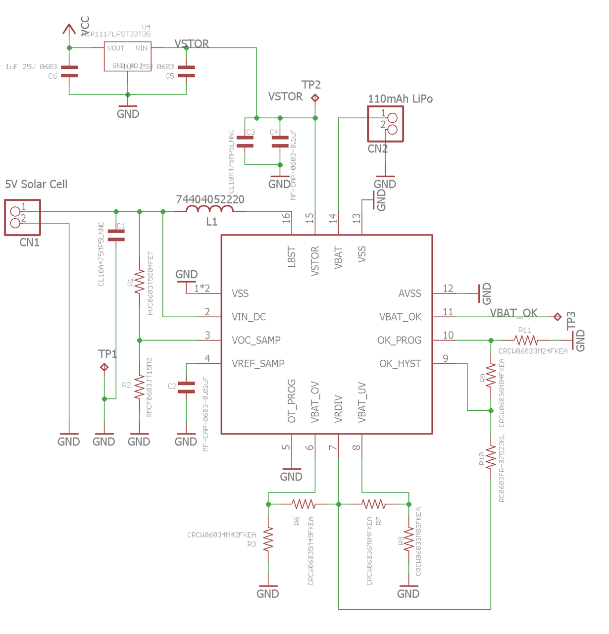
    I have attached a schematic of my power supply section, in case there are any glaring mistakes there. Thanks again,

    Jarek

  • Jarek,

    When the circuit transmits and draws the 250mA, your VSTOR voltage may be dipping below the VBAT_UV threshold just enough to disconnect VSTOR and VBAT. There is an internal PFET that connects VBAT to VSTOR once cold start is done and the main boost charger takes over. But, if VSTOR dips below the VBAT_UV threshold the PFET will open up. This feature keeps the battery from being over discharged.

    I see two options. One being what you said, increase the capacitance on VSTOR to handle the current draw. Another option would be to lower your VBAT_UV threshold, I see it is set to 3.22V.

    Observation:
    I notice you are using an LDO to lower the voltage going to the rest of your circuit. I don't know if you are aware of the BQ25570. This energy harvester is essentially the same as the BQ25504 but has a regulated buck output rail. This could replace the LDO you are using and provide a more efficient power rail to the rest of you circuit.

    Two things to keep in mind:
    1. The max output current of the buck is 110mA.
    2. the VBAT_UV threshold is internally set to 1.95V.

    If your transmitter circuit requires the whole 250mA and/or 1.95V for VBAT_UV is too low then nevermind! But, I thought I would throw it in the mix.

    Best Regards,

    Joe
  • Thanks for the clarification! I see how my application just runs into the safety feature.

    I have a few other resistor values on hand, so I'll try swapping out the VBAT_UV resistors to set it to 1.95. If the circuit works, I'll look into the BQ25570, thanks for the tip!