This thread has been locked.

If you have a related question, please click the "Ask a related question" button in the top right corner. The newly created question will be automatically linked to this question.

BQ24616: Failure of device when battery connected with no ACPWR supplied.

Part Number: BQ24616

I am having an issue with the bq24616RGET device. The design has been taken from the bq2461x/bq2463x EVM (HPA422) evaluation board for a 6S battery.

When no ACPWR is supplied and a LiPo (6S 25.2V) battery is connected, the device fails, taking a large inrush current which causes the sense resistor (R18 0.01R 500mW) to go open circuit. The drain to source resistance on Q4 is also affected, measuring some 33R.

I have a 6S LiPo battery pack connected through a switch to the UUT, with leads 150mm long. Could this be adding inductance?

My question is can this design be operated without supplying ACPWR or must the ACPWR initialise the device before connecting the battery?

  • Hi Geoff,

    Yes, you can connect a battery before ACPWR. What is the voltage rating of Q4 and D2? Please use plot the voltage on SW when you connecting the battery.

    Alen Chen
  • Alen Chen said:
    Hi Geoff,

    Yes, you can connect a battery before ACPWR. What is the voltage rating of Q4 and D2? Please use plot the voltage on SW when you connecting the battery.

    Alen Chen

    Hi Alen,

    Thanks very much for the response.

    First of all that is good news that ACPWR is not needed before connecting the battery. The battery 'jumps starts' the design in this case.

    The high and low side MOSFETs Q3 and Q4 respectively, are Vishay SI7148DP-T1 and have a Vds of 75V. The gate charge is nominally 33nC.

    D2 is not in the design as it is not populated on the EVM I have. I have just checked the TI BOM and none are specified although the description is for a MBRS140 1A, 40V. Is D2 recommended?

    The design is set for 5A charging with L1 set at 3u3H, 9A. The bank of 10uF capacitors C20, C23, C25 and C27 are 50V X5R. Must these have a low ESR?

    I have very closely followed the layout with reference to the HPA422 EVM bq24616 sluu396a.

    Before blowing another bq24616, I have added a 10k pull-down to PGND to the gate of Q4, and a 10k from the gate of Q3 to the source.

    I have also added a  24V SMBJ24 TVS to the VBAT line and removed C17 to the 100nF cap from SRP to GND.

    I will attempt to take a 'scope trace of the battery connection as referred to the issues experienced in the post in this link.

    https://e2e.ti.com/support/power_management/battery_management/f/179/p/101343/355726#355726/


    Any further suggestions would be most welcome.

    Thanks for your help.

    Geoff

  • Hi Geoff,

    How long is your cable for battery? Please try to use a short cable to connect the battery. TVS is helpful.

    Can you repeat it?

    Alen Chen
  • Hi Alen,

    Before a further board was tested with a 6S LiPo pack, a 4S was tried. This did not cause any problems. Does this suggest the voltage of 25.2V is close to or above the design limits?

    In answer to your question, the battery cable is 4mm square wire, 150mm long with a 20A rated switch in series with the battery +ve line.

    The battery is connected through an XT60 connector.

    The reason the switch was added is because the first time this happened, when the XT60 connector was connected there was an immediate crack and a flash. The switch can be operated faster than connecting and disconnecting the XT60.

    This connection method also caused a failure on the HPA422 EVM board taking out the gate pin of Q4, the lowside MOSFET. This went short circuit to PGND.

    I have noticed on the EVM board that contrary to some posts, that C17 is populated and C21 is not. This is around the sense resistor connected to the SRP and SRN pins.

    I will replace the bq24616 and temporarily add a 1R 100W series resistor back in. This will allow some measurements to be taken, but the resistor is not a final option.

    I may add a TVS to the PH pin, together with one already connected to the battery connection.

    Any more suggestions would be most helpful. Thank you for your help.

    Regards

    Geoff

  • Hi Alen,
    Further testing has revealed that the following.
    With no UUT connected to the cable and switch assembly, a 'scope trace shows that when the switch is thrown, the battery supply overshoots up to 31V before settling to its static supply of 22.4V.
    With no bq24616 device fitted, the battery and switch assembly were connected.
    When the switch was thrown, the lowside MOSFET Q4 failed shorting D-S and measuring 33R from G-S.
    Even with a 10k pull-down from Q4/G to PGND, possibly the 'Miller Effect' between Q$/D and Gate maybe enough to pull it on.
    The maximum rating of PH is 30V but recommends 28V, and LODRV is limited to 7V.
    I have ordered a TVS which clamps at 26V and a 6V2 zener for the respective points.
    I'll let you know.

    Regards

    Geoff
  • Hi Geoff,

    Do you means a 4S battery is OK for the circuit? Doesn't meet any problem? Can you send the waveform with SRN SRP to me? What is UUT? Please add the TVS on SRN instead of PH, If you add the TVS on PH It will bring too much parasitism capacitance on PH Pin.

    In order to reduce the overshot voltage, You also can try to add a snubber on SRN like R1,R2, C2,C32 on the EVM schematic.

    Alen Chen
  • Hi Alen,

    Yes the 4S LiPo pack at 16.8V did not cause a failure with the switch assembly, but the 6S does.

    UUT is the 'unit under test' which means the whole PCB assembly was disconnected from the switch and battery assembly.

    The UUT now has Q4 and the bq24616 removed for safety, until the waveforms below are within the design parameters.

    Here the SRN (yellow) and SRP (blue) overshoot. SRP measures 33.^v

    This trace is taken with a 3R9 resistor in series with C20 10nF 50V to create a snubber across SRN and PGND. C23, C25 and C27 have been removed.

    this is worse but reduces the ringing. C17 was removed at this point and C21 (100nF fitted)

    One further concern is that in all traces, the voltage drop across R18 (10mR 500mW) is 2V. That is a lot of current. L1 is a 3u3H shielded SM inductor with a resistance of 17.7mR in accordance with the design specification.

    I see on the EVM schematic R19 is shown as 0R. I did not design this in but I guess there was a reason it is there as a snubber. C21 is not stated nor fitted.

    I will add the TVS which is rated to clamp at 26V to SRN and not the PH pin.

    Regards

    Geoff

  • HI Geoff,

    Thanks for the waveform. It looks a over voltage problem.  Please don't remove output capacitor when you add the snubber. Waiting for the test with TVS.

    For R18, please check CH1 and CH2 on your scope is matched or not.  You also can consult to the resister vender.

    Alen Chen 

  • Hi Alen,

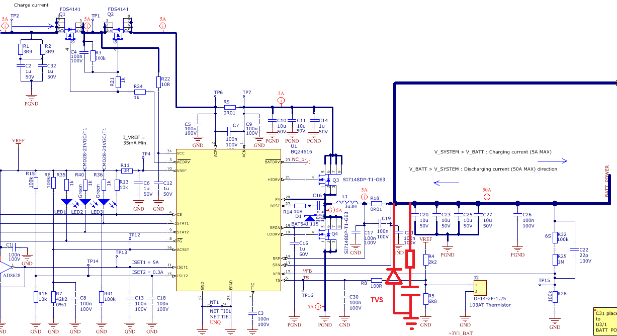
    I am still having issues with the bq24616 having added an SMBJ16 TVS diode (clamping at 26V) from the R18/SRN junction to PGND plus I have added a snubber circuit to the same point.

    The battery lead has now been shortened to 100mm with no switch. The battery was connected successfully three times but on the fourth, the bq24616 cracked and smoked in the area of pins 19, 20 and 21. Q4 D-S measured 69R.

    I experimented with the snubber circuit and derived the values from established equations.

    The traces of SRN and SRP are here: The overshoot is within tolerance of the bq24616 suggesting the TVS and or the snubber are suppressing the ringing compared to the previous post.

    One further point is that the sense resistor R18 at least did not go open circuit this time.

    The schematic is here with the TVS and snubber 1k + 1nf  in red.

    I am running out of ideas and wonder if others on the forum have found a solution.

    Any further ideas would be gratefully received please.

    Regards

    Geoff

  • Hi Geoff,

    What is the difference between the previous 3 time and the last time plugging in the battery? Is there any abnormal operation in the previous 3 time?

    Best regards,
    Ann Lien
  • Hi Geoff,

    If the TVS and the snnuber still can't solved the problem,  Please try to use a PFET between battery caps and battery connector  to reduce the inrush current and overshot.  Please refer to below circuit, You can modify the values to modify the time of tun on. hope it helps 

    Thnaks.

    Alen Chen

  • Hi Alen,

    Thanks for the advice. I'll update you with where I am first.

    In reply to your last post, nothing was different from the fourth connection of the battery compared to the first three times. The connection of +ve or -ve terminals may be random.

    Several modifications were added in one sweep as we cannot afford to destroy too many boards.

    The snubber was added together with a TVS, D2 (MBRS130 Q4/S to PGND), C17 removed, C21, 27v zener connected across VCC, 10k pull downs from Q4/G and Q3/G. D1 was uprated to 500mA schottky PMEG40005H. A more direct path from the Net Tie was added by cutting this and adding a direct connection from the U1 thermal pad to PGND at the battery terminal input.

    After all these modifications, the TVS blew but no other damage was obvious.

    In response to the above circuit, this ties in with a temporary solution we have come up with which is to use the balance connector on our LiPo pack.

    With a fresh board and no modifications the battery pack connects to our battery terminals through a 1K/1W resistor precharging the capacitors.

    Provided this connects first, followed by the charge connector, all is well. The board has been shown to charge up the pack starting at 2A, ramping down to zero, then showing STATUS2 LED lit indicating a full charge.

    It does almost prove that it is inrush issue.

    I would strongly suggest TI make an amendment to the EVM and datasheet to guide other users of perils of inrush problems. I know other shave had similar issues.

    In summary keep connecting cables short to minimise inductance and by some means pre-charge the capacitor bank before connecting your battery.

    Regards

    Geoff

  • Hi Geoff,

    You are right, thanks for you feed back. pre-charge the capacitors is very helpful. But this may need a special connector which connect battery and charger through a resistor first, than connect battery and charger directly.  So we suggest to use a PMOS (above )to implement same function. 

    Alen Chen