This thread has been locked.

If you have a related question, please click the "Ask a related question" button in the top right corner. The newly created question will be automatically linked to this question.

bq24272: Battery OVP warning

Part Number: BQ24272
Other Parts Discussed in Thread: BQ24261M, , CC3100MOD, BQ24160, BQ24168

Hello,

I have set the registers for 4.2 V operation. A lot of times the Battery OVP (overvoltage error occurs).

I would like to know at which battery voltage level the Charger IC quits draining the battery.

And when (if) it finally stops showing the error due to draining, will the charger IC then resume normal charging?

Is there any way to stop the draining when I detect the Battery OVP? I would like to enter a state equal to charge done in order not to drain the battery..

HC

  • Hey Hans,

    The battery OVP threshold could typically be anywhere between 2.5 - 7.5% higher than VBATREG, which you set to 4.2V, which is spec'ed and labeled in the datasheet EC table as "V_BOVP" under the Input Protection section.

    Also, please be aware that this part has a watchdog timer, which once expired, will return VBATREG to default value of 3.6V.

    Lastly, you may also want to look at the bq24261M as an alternative solution to your project. We have NRND'ed this device.


    Regards,
    Joel H
  • Hello Joel,

    I am constantly resetting the watchdog.

    However, I could not find any information about what will happen when the battery voltage falls below the the threshold. Will it resume normal charging?

    I am aware of the new (non-pin-replaceable)  IC. The IC was designed into the product some years ago (yeah long project).

    The point is: I need to find a solution that avoids the battery overvoltage problem with the current IC.

    Could you elaborate some of why you have NRND'ed this device - what is the "known" issue with it? Could not find any errata...

  • Hey Hans,

    Yes, it should resume normal charging. Typically, you won't see any charge again until the voltage the VBAT voltage crosses the Recharge threshold.

    And the part was NRND'ed for several reasons, including newer and improved IP that was released later, and just a general business decision to push more customers to these parts.


    Regards,
    Joel H
  • Hans,

    Can you send all the registers before and after you get the BATOVP warning?
  • Jeff,

    I only set my registers according to the code below. Then I constantly every 5 sec reset the watchdog.
    I also display all the status warnings on a display continuously while charging.

    // Sets and verifies registers. Returns False if error.
    // Standard charge method is 0.2C CC charge to 4.2V/cell, then CV charge till the charge current decline to 0.02C.
    // CC: 5h (90%) + CV: 0.5h = 5.5h
    _Bool I2C_ChargerSetRegisters()
    {
    _Bool error;
    struct st_BQ24272 *pBQ24272;

    // 01
    BQ24272.STATUS_CONTROL.BIT.TMR_RST = 1; // Reset Watchdog timer
    I2C_ChargerWriteReg(BQ24272.STATUS_CONTROL.BYTE, STATUS_CONTROL_ADDR);

    // One writable field: EN_NOBATOP - should be default.
    //BQ24272.BATTERY_SUPPLY_STATUS

    // 02
    BQ24272.CONTROL.BIT.RESET = 0; // No reset
    BQ24272.CONTROL.BIT.EN_STAT = 0; // Disable STAT output (we dont use it)
    BQ24272.CONTROL.BIT.TE = 1; // Enable charge current termination.
    BQ24272.CONTROL.BIT.CE_N = 0; // Charger enabled.
    BQ24272.CONTROL.BIT.HZ_MODE = 0; // Not HZ mode

    I2C_ChargerWriteReg(BQ24272.CONTROL.BYTE, CONTROL_ADDR);

    // 03
    // Offset 3.5V, set to 4.2V
    BQ24272.CONTROL_BATTERY_VOLTAGE.BIT.VBREG5 = 1; // 640 mV
    BQ24272.CONTROL_BATTERY_VOLTAGE.BIT.VBREG4 = 0; // 320 mV
    BQ24272.CONTROL_BATTERY_VOLTAGE.BIT.VBREG3 = 0; // 160 mV
    BQ24272.CONTROL_BATTERY_VOLTAGE.BIT.VBREG2 = 0; // 80 mV
    BQ24272.CONTROL_BATTERY_VOLTAGE.BIT.VBREG1 = 1; // 40 mV
    BQ24272.CONTROL_BATTERY_VOLTAGE.BIT.VBREG0 = 1; // 20 mV
    BQ24272.CONTROL_BATTERY_VOLTAGE.BIT.I_INLIMIT = 0; // 1.5A limit for input current.

    I2C_ChargerWriteReg(BQ24272.CONTROL_BATTERY_VOLTAGE.BYTE, CONTROL_BATTERY_VOLTAGE_ADDR);

    // Read only register
    //BQ24272.VENDER_PART_REVISION

    // 05
    // Charge current sense offset is 550mA: 2500 mAh battery, 0.2C => 500 mA (use 550 mA)
    // Termination threshold offset is 50mA: 2500 mAh battery, 0.02C => 50 mA
    BQ24272.BATTERY_TERMINATION_FAST_CHARGE_CURRENT.BIT.ICHRG4 = 0; // 1200 mA
    BQ24272.BATTERY_TERMINATION_FAST_CHARGE_CURRENT.BIT.ICHRG3 = 0; // 600 mA
    BQ24272.BATTERY_TERMINATION_FAST_CHARGE_CURRENT.BIT.ICHRG2 = 0; // 300 mA
    BQ24272.BATTERY_TERMINATION_FAST_CHARGE_CURRENT.BIT.ICHRG1 = 0; // 150 mA
    BQ24272.BATTERY_TERMINATION_FAST_CHARGE_CURRENT.BIT.ICHRG0 = 0; // 75 mA
    // Termination (current level when end of charging).
    BQ24272.BATTERY_TERMINATION_FAST_CHARGE_CURRENT.BIT.ITERM2 = 0; // 200 mA
    BQ24272.BATTERY_TERMINATION_FAST_CHARGE_CURRENT.BIT.ITERM1 = 0; // 100 mA
    BQ24272.BATTERY_TERMINATION_FAST_CHARGE_CURRENT.BIT.ITERM0 = 0; // 50 mA

    I2C_ChargerWriteReg(BQ24272.BATTERY_TERMINATION_FAST_CHARGE_CURRENT.BYTE, BATTERY_TERMINATION_FAST_CHARGE_CURRENT_ADDR);

    // 06
    // VIN-DPM voltage offset is 4.20 V: (Set to 4.52 V before, now 4.2V 2015!)
    // This feature will lower charge current if inpout voltage gets below threshold.
    BQ24272.V_IN_DPM_VOLTAGE_DPPM_STATUS.BIT.V_INDPM2 = 0; // 320 mV
    BQ24272.V_IN_DPM_VOLTAGE_DPPM_STATUS.BIT.V_INDPM1 = 0; // 160 mV
    BQ24272.V_IN_DPM_VOLTAGE_DPPM_STATUS.BIT.V_INDPM0 = 0; // 80 mV

    I2C_ChargerWriteReg(BQ24272.V_IN_DPM_VOLTAGE_DPPM_STATUS.BYTE, V_IN_DPM_VOLTAGE_DPPM_STATUS_ADDR);

    //BQ24272.SAFETY_TIMER_NTC_MONITOR
    BQ24272.SAFETY_TIMER_NTC_MONITOR.BIT.XTMR_EN = 0; // Timer not slowed down.
    BQ24272.SAFETY_TIMER_NTC_MONITOR.BIT.TMR = 1; // 6 hour faste charge.
    BQ24272.SAFETY_TIMER_NTC_MONITOR.BIT.TS_EN = 1; // NTC Temp monitor on.
    BQ24272.SAFETY_TIMER_NTC_MONITOR.BIT.LOW_CHG = 0; // Charge current as programmed in reg 0x05;

    I2C_ChargerWriteReg(BQ24272.SAFETY_TIMER_NTC_MONITOR.BYTE, SAFETY_TIMER_NTC_MONITOR_ADDR);

    // Read and verify registers
    pBQ24272 = I2C_ChargerReadRegistersAndGetStatus();

    error = false;
    if ( (pBQ24272->BATTERY_SUPPLY_STATUS.BYTE & 0x01) != 0x00 )
    {
    error = true;
    }

    if ( (pBQ24272->CONTROL.BYTE & 0x8F) != 0x84 )
    {
    error = true;
    }

    if ( (pBQ24272->CONTROL_BATTERY_VOLTAGE.BYTE & 0xFE) != 0x8C )
    {
    error = true;
    }

    if ( (pBQ24272->BATTERY_TERMINATION_FAST_CHARGE_CURRENT.BYTE & 0xFF) != 0x00 )
    {
    error = true;
    }

    if ( (pBQ24272->V_IN_DPM_VOLTAGE_DPPM_STATUS.BYTE & 0x07) != 0x00 ) // 0x04 to 0x00 change above!
    {
    error = true;
    }

    if ( (pBQ24272->SAFETY_TIMER_NTC_MONITOR.BYTE & 0xE9) != 0x28 )
    {
    error = true;
    }

    return (!error);

    }


    -------

    // Registers
    #pragma bit_order left
    #pragma unpack
    struct st_BQ24272 {
    // 00
    union {
    unsigned char BYTE;
    struct {
    unsigned char TMR_RST:1;
    unsigned char STAT:3;
    unsigned char :1;
    unsigned char FAULT:3;
    } BIT;
    } STATUS_CONTROL;

    // 01
    union {
    unsigned char BYTE;
    struct {
    unsigned char STAT:2;
    unsigned char :3;
    unsigned char BATSTAT:2;
    unsigned char EN_NOBATOP:1;
    } BIT;
    } BATTERY_SUPPLY_STATUS;

    // 02
    union {
    unsigned char BYTE;
    struct {
    unsigned char RESET:1;
    unsigned char :3;
    unsigned char EN_STAT:1;
    unsigned char TE:1;
    unsigned char CE_N:1;
    unsigned char HZ_MODE:1;
    } BIT;
    } CONTROL;

    // 03
    union {
    unsigned char BYTE;
    struct {
    unsigned char VBREG5:1;
    unsigned char VBREG4:1;
    unsigned char VBREG3:1;
    unsigned char VBREG2:1;
    unsigned char VBREG1:1;
    unsigned char VBREG0:1;
    unsigned char I_INLIMIT:1;
    unsigned char :1;
    } BIT;
    } CONTROL_BATTERY_VOLTAGE;

    // 04
    union {
    unsigned char BYTE;
    struct {
    unsigned char VENDER:3;
    unsigned char PN:2;
    unsigned char REVISION:3;
    } BIT;
    } VENDER_PART_REVISION;

    // 05
    union {
    unsigned char BYTE;
    struct {
    unsigned char ICHRG4:1;
    unsigned char ICHRG3:1;
    unsigned char ICHRG2:1;
    unsigned char ICHRG1:1;
    unsigned char ICHRG0:1;
    unsigned char ITERM2:1;
    unsigned char ITERM1:1;
    unsigned char ITERM0:1;
    } BIT;
    } BATTERY_TERMINATION_FAST_CHARGE_CURRENT;

    // 06
    union {
    unsigned char BYTE;
    struct {
    unsigned char MINSYS_STATUS:1;
    unsigned char DPM_STATUS:1;
    unsigned char :3;
    unsigned char V_INDPM2:1;
    unsigned char V_INDPM1:1;
    unsigned char V_INDPM0:1;
    } BIT;
    } V_IN_DPM_VOLTAGE_DPPM_STATUS;

    // 07
    union {
    unsigned char BYTE;
    struct {
    unsigned char XTMR_EN:1;
    unsigned char TMR:2;
    unsigned char :1;
    unsigned char TS_EN:1;
    unsigned char TS_FAULT:2;
    unsigned char LOW_CHG:1;
    } BIT;
    } SAFETY_TIMER_NTC_MONITOR;

    };
    #pragma bit_order
    #pragma packoption
  • Hans,

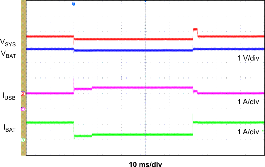
    The status registers may be reporting an error that can help trace the BOVP fault.   In addition, scope plots showing V(SYS), V(BAT) and triggering of I(SYS) during a load transient would be helpful to rule out the possibility of V(SYS) overshoot on load transient recovery.  An example load transient showing V(SYS) (red) overshoot after leaving supplement mode is below.  Does the fault only happen when the battery is close to full charge?  Where is V(TS) when this happens?

  • Jeff,

    Thanks for your reply, and sorry for my late reply.

    To answer your question: Yes, the BOVP fault only happens when the battery is close to full charge. Could this late stage somehow trigger the BOVP?

    I will implement a variable to check if DONE occurs before the error occurs - in order to check if it reaches DONE before the error.

    With respect to V(TS), I have not checked the voltage at the temp sensor input.

    I will implement a GPIO to output a signal when the BOVP occurs in order to trigger the scope, and measure VSYS, VBAT and IBAT during this event.

    HC

  • Hi,

    I have done some measurements to see what is happening. When I conducted the measurement I did not encounter the BOVP fault - however something else interesting occurred.

    I measured the battery current. I have set the termination to 50 mA. When it reached about 28 mA flowing into the battery, it suddenly reversed and the current started to flow from the battery into the circuit at about 5 mA (measured by multimeter and uCurrent device). Not any of the status registers changed! It was still reporting "charging". I suspect that the 5 mA reading is due to capacitive coupling through the battery-FET (which I assume is off now) due to the oscillation seen in the picture below. (Measuring the BAT pins shows some noise coupling due to the "noise" on the SYS.)

    Then I measured the SYS voltage with an oscilloscope. Have a look at the waveform in the picture.

    The SYS voltage is oscillating between about 4.2V and 4.4V with a 50% duty and period of 2 ms.

    In the datasheet there is something called V_SYSREGFETOFF which is the system regulation voltage when termination is reached. V_BATREG +4.17% is the maximum and looks consistent to the 4.4V half-period peak. However, I have not any clue what is actually happening here and why V_SYS is behaving this way. 

    The measured termination current is some below the accuracy stated in the datasheet which is: +/- 35% for 50 mA.

    An other interesting observation is that if the battery practically is fully charged, (lets say the charging current is between 50 and 70 mA), and you take the DC jack out and in again within some seconds, it will report DONE immediately. However, if you don't do that, the charging current will just drop down until reaching the 28 mA limt... In my setup I have a message queue which wakes up CC3100MOD. If this is called during the "long time to 28 mA" phase, DONE is reported. Waking the CC3100MOD consumes some current briefly. Why would a "surge" current on V_SYS sort of make the charger IC suddenly start to behave correctly?

    It seems to me that the IC is not able to correctly end the constant voltage phase at the set termination current and enter DONE.

    I tried to conduct some tests where I first reset the charger IC (reset Bit) and then set the register settings to check if this "restart" during the "actually fully charged battery phase" will have equal behavior as: taking in and out the DC plug / force a sudden inrush current on V_SYS.

    Answer: The restarting would often result in a BOVP error, and it will stay stuck in that error state. However, if I wakeup the CC3100MOD it gets out of the BOVP error state, and returns to normal charging.  If I already have the CC3100MOD on, and then restart the charger IC it will briefly enter BOVP state and return to normal charging.

    I mapped the control of sleep/wakeup of CC3100MOD and the charger IC restarting to some buttons.

    It would be interesting if these observations could reveal the root cause for this odd behavior. 

    HC 

  • HC,

    Adding a current meter in series with the battery is generally not recommended. If you short the meter, does the oscillation go away? If so, then it is a setup issue. If not,

    The bq24272 is a spin of the bq24160. The oscillation and termination issues that you are seeing may be due to false tripping of the reverse boost detection circuitry as explained 9.3.16.5 Reverse Boost (Boost Back) Prevention Circuit of www.ti.com/.../bq24168.pdf. If you write a 1 to memory location bit 0 (EN_NOBATOP) to disable the reverse boost prevention circuit, does the oscillation go away? If so, then I recommend using this bit when the battery is close to termination in order to low charge current termination. However, there is a risk that fully charged battery will boost back to the input voltage (in other words, you might see spikes of up to 10V appear on the IN pin). This will not damage the charger IC.
  • Jeff,

    The sense resistor is only 10 mOhm (so very low burden voltage), so I guess it should not matter. The oscillation did not go away when shorting the sense resistor.

    Could you emphasize what you mean by: "... then I recommend using this bit when the battery is close to termination in order to low charge current termination".

    What do you mean by "in order to low charge current termination"?

    If it helps to set EN_NOBATOP to '1' when the battery is close to termination, how would I know when the battery is close to termination? My application is set in stone - at lest to my wishes(!)

    However, luckily (perhaps) for me I have placed an AD MCU 12bit pin on the SYS output. Could I monitor this pin and assume when the voltage is about 4.2V (and not increasing anymore) that the charger is in CV phase - and then say/state that we are close to termination and set EN_NOBATOP bit? Figure 2. in the datasheet would lead me to think that this is possible. I could also wait for a default constant time after detecting 4.2V to set EN_NOBATOP if this would help of course...

    --

    Another observation: The current is now 100 mA. If I reset the charger by means of setting the reset bit in the control register, BVOP is reported. This makes sense since the batt voltage is now set to 3.7V (default reset). If I then after the resetting set the correct register settings, BVOP fault state is not exited/cleared. The only way to exit the error state is to start the wifi chipset or take out and in the DC jack.

    After reading the bq24168 pdf, there was a method on how to clear BOVP fault. Set the HZ mode! So I toggle it:

    void I2C_ChargerClearBatteryOVPfault()
    {
      // 02
      BQ24272.CONTROL.BIT.RESET = 0;        // No reset
      BQ24272.CONTROL.BIT.EN_STAT = 0;      // Disable STAT output (we dont use it)
      BQ24272.CONTROL.BIT.TE = 1;           // Enable charge current termination.
      BQ24272.CONTROL.BIT.CE_N = 0;         // Charger enabled.
      BQ24272.CONTROL.BIT.HZ_MODE = 1;      // HZ mode
      I2C_ChargerWriteReg(BQ24272.CONTROL.BYTE, CONTROL_ADDR);  
      
      BQ24272.CONTROL.BIT.HZ_MODE = 0;      // Not HZ mode
      I2C_ChargerWriteReg(BQ24272.CONTROL.BYTE, CONTROL_ADDR);  
    }

    This works!

    As related to the VSYS oscillation/pulse issue: Since my application is able to detect the voltage oscillation by means of the AD pin, this error state can be detected. As you said, setting the EN_NOBATOP bit after I detect the oscillation will remove the oscillation. Clearing the EN_NOBATOP to normal just afterwards seems to be OK. During the testing I now see termination at about 25 mA. This is far away from the expected 50 mA - but I guess I can live with that? Or will this have bad impact on the battery?

    HC

    HC

  • HC,

    Sorry, should have been "in order to ALLOW low current termination". If you were too have used ITERM=150mA, you might not have seen this issue.

    Setting HiZ mode resets everything but be careful because in HiZ mode the only power to your system from the battery. The buck converter is turned off and will not provide the MINSYS voltage at SYS. BVOP should reset if you simply write VBATREG register up to 4.2V from the default 3.6V.

    I like your idea about the ADC to monitor the voltage level and only change the EN_NOTBAOP bit when close to termination.

    The datasheet min spec for ITERM=50mA is +/-35% so you should be terminating at 32mA at a minimum. How accurate is your ITERM = 25mA measurement?