This thread has been locked.

If you have a related question, please click the "Ask a related question" button in the top right corner. The newly created question will be automatically linked to this question.

BQ24618: REGN unstable / LODRV not switching properly

Part Number: BQ24618

Hi,

I am trying to build a 6 cell / 2A Li-Ion charger using BQ24618.

So far my prototype is charging the battery, but the n-FET (I'm using a Si7288DP dual n-FET) is getting very hot quickly (it reaches 60°C within a minute or so).

From the scope traces it seems to me that REGN is unstable and LODRV not switching properly:

Channels from top to bottom: REGN, HIDRV, LODRV, PH

Channels from top to bottom: REGN, HIDRV, LODRV, PH.

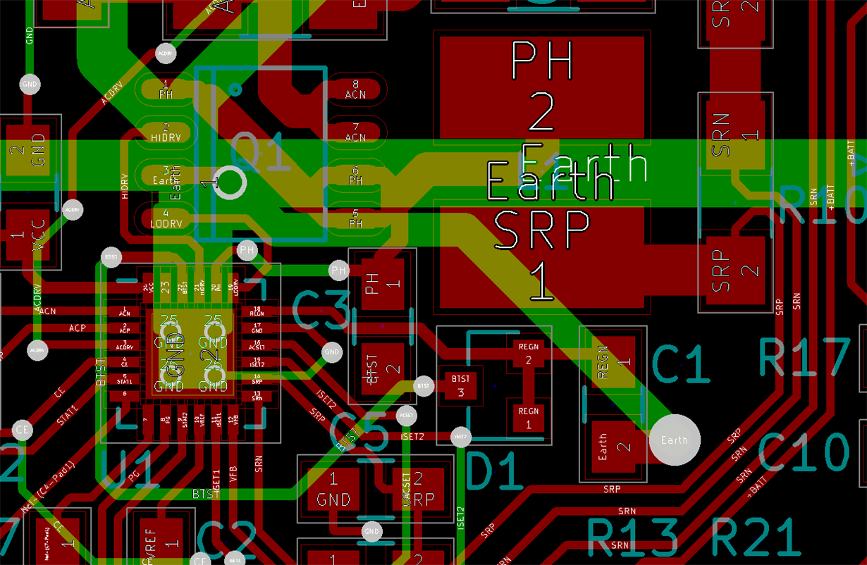
The schematic is closely based on the reference design given in the datasheet (attached below) and the PCB section of the buck converter looks like that:

0550.charger.pdf

I'd appreciate any advise on how to further debug & fix this issue.


Regards,

Jens

  • Hello,

    Can you check that is there any short condition, and give me your voltage information of IC's pins(like VCC, VBAT).

    Regards

  • Hi Kerry,

    thanks for your quick reply.

    I just double checked all nets connected to the BQ24618 as well as input & output for shorts and did not find any (everything except for the current sense pins measured at least several kOhms).

    VCC is 27V (currently generated by a linear lab supply) and VBAT is set to a maximum of about 25.2V, with the battery I use for testings connected it's about 23V while charging.

    Here's a scope shot of VCC in during charging:

    Ch1. is VCC, the others are LODRV, HIDRV and PH as in my previous post.

  • Hello

    From the waveform, it seems that the BUCK haven't be open/closed normally, you could refer to P13 in datasheet for normal switching waveform. Please check if the connection of your board's buck is right. Could you capture the waveform for several cycle in one picture, includes IL, HIDRV, PH, VCC waveform.

    You say "current sense pins measured at least several k ohm", it's not normal. the current sensor is too big, so IC will judge your current is too large, then start protection and close the charging process. please solve the issue on your board.

    Regards

  • Hi Kerry,

    sorry for the late reply, but unfortunately I didn't get to spend any time on this project until now...

    Kerry Song said:
    You say "current sense pins measured at least several k ohm", it's not normal. the current sensor is too big, so IC will judge your current is too large, then start protection and close the charging process. please solve the issue on your board.

    You misunderstood me there: the current sense inputs (ACN/ACP and SRN/SRP) measured as short on my multimeter (since the 10mOhm resistor between those pins is way below the minimum resistance the meter is able to measure). All other adjacent pins on the BQ24618 measured in the kOhm range.

    Anyway here are the waveforms you requested:

    The waveform are from top to bottom: VCC, HIDRV, PH, I_BAT (channel 4's zero point is excatly at the bottom of the screen, the arrow indicator is misleading). Battery current has been measured using a 1 Ohm shunt in series with the battery's ground connection.

    Regards,

    Jens

  • Hello,

    I  am looing into this, and will give you my analysis later.

    Regards

  • Hi Kerry,

    do you have any news for me regarding your analysis?

    Regards,

    Jens

  • Hi Jens,

    Sorry for the late reply.
    So the charging function is normal, right? The only issue is MOSFET get hot quickly. Is it in CCM or DCM mode when you captured the waveform in your first post? It seems HIDRV in your design is unstable. From Kerry's recommendation, could you please plot inductor current not battery current for us? Like PH, HIDRV, LODRV and inductor current. We need these to analysis.

    And If it is possible, could you provide the PCB file of bq24618 portion? We also need to check if there is an error in layout.

    Thanks,
    Ann Lien
  • Hi Ann,

    thank you for your reply, here are the schematic and PCB files (in kicad format):

    charger.zip

    The BQ24618 should operate in CC mode during all captures (the battery's voltage is about 22V, VFB is set to 25.2V).

    It seems to be charging alright (does not exceed set current), but I did not check if CV mode or charge termination work correctly, as  I'm afraid the MOSFET will not survive a full charge cycle at the rate it's heating up.

    I will try to capture some traces of the inductor current as soon as I get in the lab tomorrow.

    Regards,

    Jens

  • Here are the requested scope traces:

    CH1 is HIDRV, CH2 is LOWDRV, CH3 is PH and the math channel is inductor current.

    The inductor current is measured using a 1ohm shunt resistor between the PH and the inductor (so 1V equals ~1A). I do not have a differential probe so I had to use the math channel to substract CH4 from CH3. The result was rather noisy, so I enabled 16 sample averaging, which the scope can only do for all channels.

    Here's single pulse without averaging, for comparision:

    Regards,

    Jens

  • Hi Jens,

    Sorry for the inconvenience. But could you send the Altium Designer format to me? I cannot open kicad format file. And could you measure inductor current by current probe? We're hard to analysis with them because of the noise(even averaging).

    MOSFET gets hot because of switching and conductive loss. Could you check if this MOSFET is suitable for your design or it just would get hot when it is in normal operation?

    Thanks,
    Ann Lien
  • Hi,

    Ann_Lien said:
    Sorry for the inconvenience. But could you send the Altium Designer format to me? I cannot open kicad format file.

    Sorry, I don't have an Altium license. If you cannot install kicad (it's available for free from ), I exported the PCB as gerber and PDF for you:

    charger-gerber-pdf.zip

    And could you measure inductor current by current probe? We're hard to analysis with them because of the noise(even averaging).

    Unfortunately I do not have access to a current probe. I'll have another go at it tomorrow, maybe I can get the noise down using different settings and/or additional filtering.

    MOSFET gets hot because of switching and conductive loss. Could you check if this MOSFET is suitable for your design or it just would get hot when it is in normal operation?

    The MOSFET is a Vishay SI7288DP.

    Datasheet:

    It has a R_DS(on) of less than 0.022 Ohm, Q_GD of 1.5nC and Q_G smaller than 15nC.

    If I understand the bq24618 datasheet correctly (page 29, section 9.2.2.4), the figure-of-merrit of this MOSFET is almost the same as the SIS412DN used in the reference design, so it should be suitable?

    Regards,

    Jens

  • Hi Jens,

    Thanks for providing sofeware link to me. I will install it and review to check if there is any clue in this issue. Please also help to check if there is anything violate the layout guideline in datashet section 12.

    For the MOSFET, it should be suitable for your design.

    Thanks,
    Ann Lien
  • I also managed to get better plots of the inductor current today, I hope these are usable:

    Channels are the same as before: CH1 = HIDRV, CH2 = LODRV, CH3 = PH, MATH = inductor current.

    The first 2 screenshots are with averaging enabled, the last one is without averaging for comparision.

    Regarding the layout guidlines: I did read that section and tried to follow these rules in my design, but I cannot rule out that I made a mistake there...

    Regards,

    Jens

  • Hi Jens,

    According to your layout, there are some recommendations.

    1. For the current sensing, you could make the ACP/ACN and SRP/SRN sensing circuit connect to Ic's pin. Should not connect to cap then connect to pin.
    2. I'm not familiar with Kicad. I want to check if there is any via in combo MOSFET earth pin. Please also take care about the distance between input cap and MOSFET, like datasheet figure 23.
    3. I'm confusing with the MOSFET package. Why you can connect D2 and S1 through one line directly? Don't it short to D1?

    Thanks,

    Ann Lien