This thread has been locked.

If you have a related question, please click the "Ask a related question" button in the top right corner. The newly created question will be automatically linked to this question.

BQ2003S stops charging after a few minutes two AA batteries in series are not charged and IC indicates they are.

Hello Team TIE2E

We are using the BQ2003S to charge 2600mAH NiMH AA batteries in series:

The IC charges for a few minutes then indicates charged but the batteries are not charged.

I have searched and cannot find any symptom similar but the issue must be in the configuration.

Can you please have a look at the configuration for automatic recharge: we are using a USB 2.4A power adapter, the current used is never beyond 750mA and 5 volts is sustained at the charge IC throughout the attempt to recharge. If we unplug usb cable, then re-plug the charge cycle starts again but then after a few minutes indicates batteries are charged...something is not correct, please help as 5,000 unit production is on hold until solved.

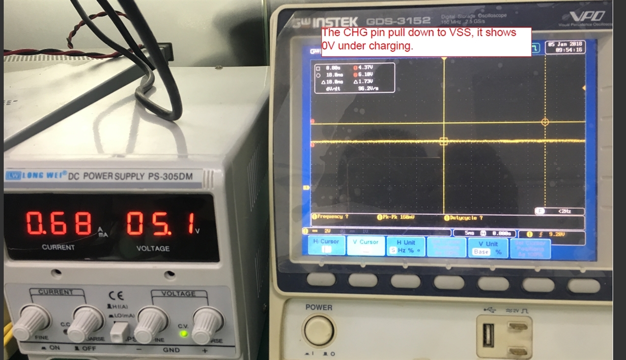
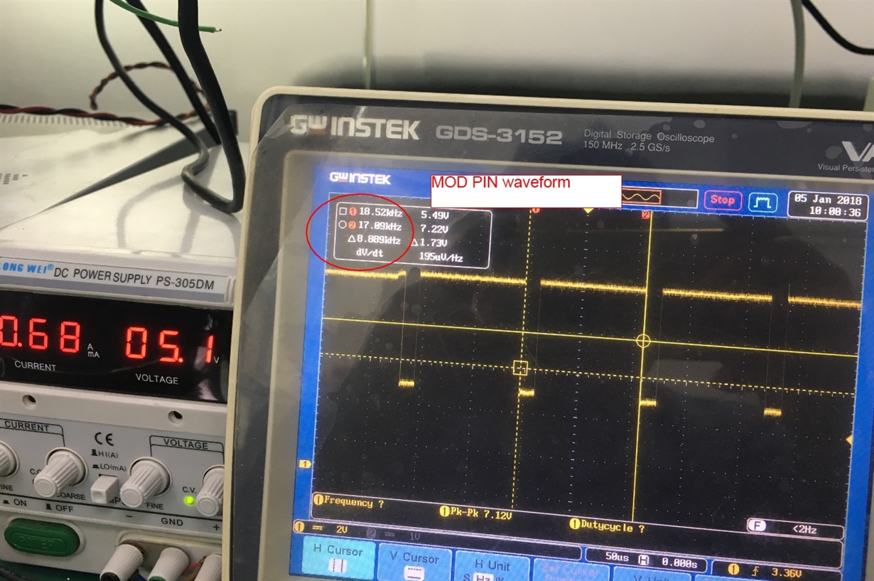
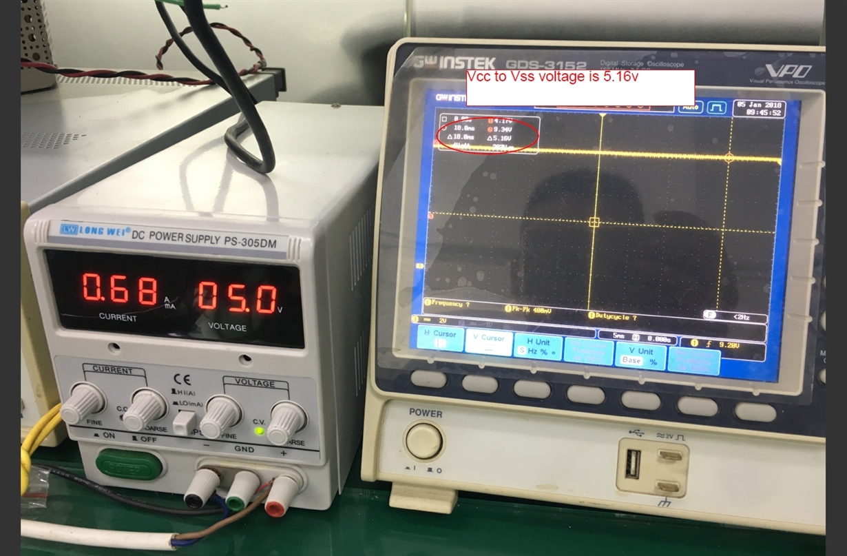
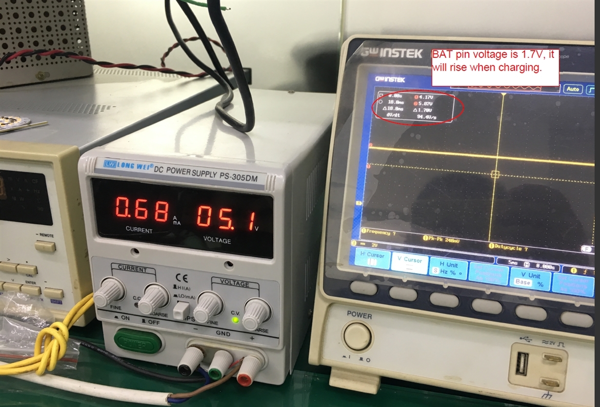
  • What is the VCC and VBAT pin voltage? Would you post a picture to show VCC, VBAT, CHG and mode pin test waveform?
  • today: I jumped PIN 8 to nearby ground to insure low resistance conduction. I also changed batteries, I suspect one or both batteries may be an issue although they arrived as NEW.
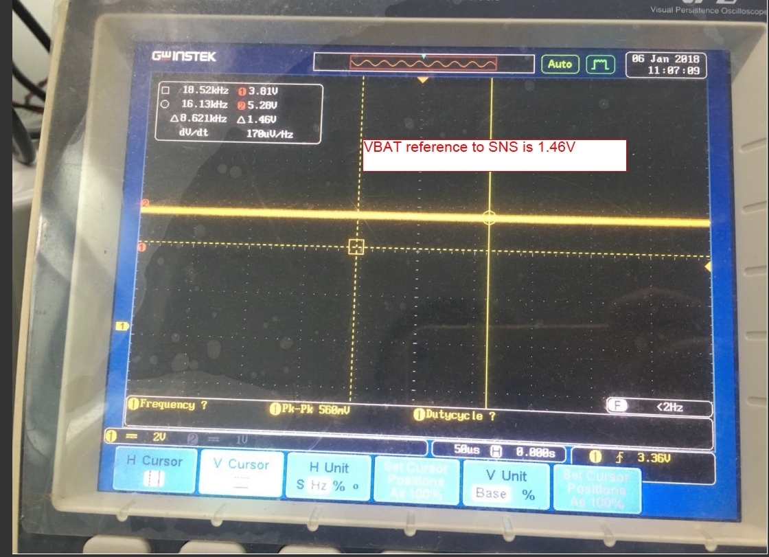
  • 1. Don't understand your waveform. Ch1 is 2V/div. Where do you put your probe ground? It seems you said Vcc is 5.16V, Vbat is 1.7V. But, they are all not use CH1 probe ground as reference.

    2. Mod pin has a 8,9kHz switching waveform. According to http://www.ti.com/lit/ug/sluu049/sluu049.pdf schematic, the switching FET Q1 should deliver power to the output. Please check Q1's gate.

    Do you test it on an EVM? Do you modify it?

  • still having same issue, short charge and not even close to capacity (2 quality AA rechargeable batteries in series)
  • I am asking on the EVM if the MOD pin has a switching waveform, does the switching waveform pass to Q1's gate or not?
  • Here is our engineer's schematic:

    LW-OS003-I.pdf

  • Good, I have the same question: does the MOD pin switching waveform pass to Q1's gate or not?
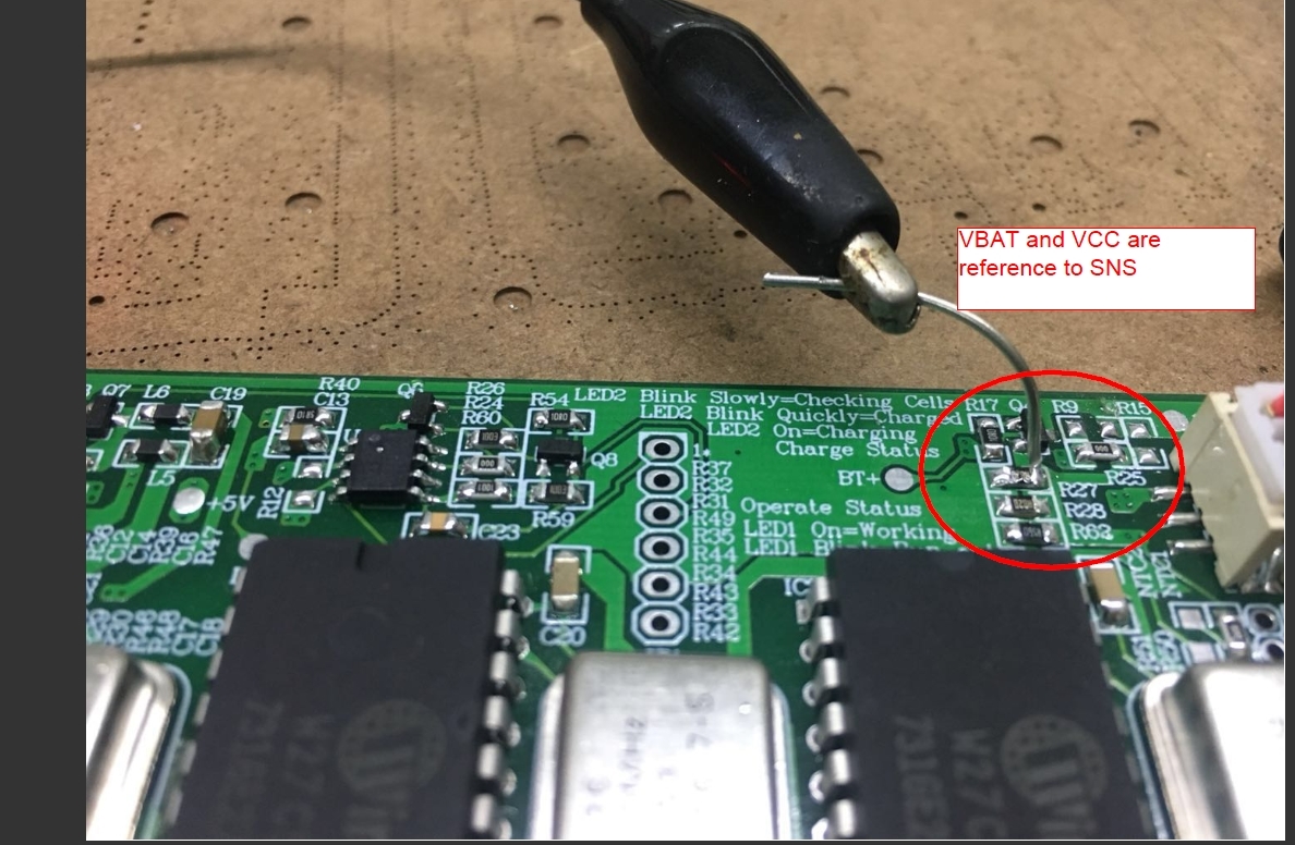
  • Here are reference points for scope measurments

  • What is the MOD pin waveform and to switching FET Q1's gate?
  • Please check this video, one is for MOD, the other is Q1 gate.

  • From the waveform, the MOD switching waveform can pass to Q1's gate. But, output doesn't get power. That means the PFET is not turned on by that Q1's gate waveform. So, Q1's gate turn-on threshold (www.onsemi.com/.../NTF5P03T3-D.PDF ) could be higher than gate drive voltage. Please increase the input voltage a little bit to see if you can get the output voltage or not. If you see a normal output voltage, that verifies the idea. And then, please try to find other low Vth FET or make the gate drive voltage a little bit higher if you can.
  • Thank you Mr. Wang, you appear to have found an important point, we will source the lower threshold FET and do a test.
    Back to you ASP with a hopeful fix, kind regards, Danny
  • Mr Wang,

    We did the change for Q5 following your prompt. But the charger did not have improvement. The waveform is as previous.  We down the input voltage to 4.3V, the MOD show high, and the Q1 completely pass.  So, we think that the mod works under PWM model when input voltage at 5.0V. We also we can hear the noise come from the inductor.

    Please advise,

    Lance, Danny

  • I didn't mention Q5 before. When MOD switching waveform is passed to Q1's gate, Q5 is not my concern. As your test result, the Q5 change doesn't increase the Q1's gate turn-on voltage. BTW, Q1 is a PFET. Turn-on means the gate is pulled down.
    Please increase the input source voltage from 5V to 7V or more, to check the Q1 can be turned on or not. That is for verifying the idea to explain why Q1 is not turned on?

    "We down the input voltage to 4.3V, the MOD show high, and the Q1 completely pass." Do you see 4.3V after Q1?

    The MOD pin frequency is 8.9k on your previous test. So, you can hear it. Let's make the circuit work. And then, check audible noise.

    For you, if there is too much trouble, just use the EVM design and 9V input source to finish your design.
  • Dear Mr Wang, please know our "Q5" in the schematic is your Q1 you are referring to. (Please see our schematic I posted previously.)

    So, when we say "Q5" we are referring to the same (P-FET) "Q1" you are referring to. Does this make sense now?

    Sorry for the confusion,

    we will increase input voltage as you suggested to see if pFET will turn on and report back to you asap.

  • Mr Wang,
    I did a test on the pcb I have here in USA and raising the voltage input to 7V did not have effect. The charge IC indicates charged in a few minutes yet the batteries are not charged anywhere near capacity. Can you have a look at the schematic while we wait for engineer from China to report findings (they used same pFET you suggested, I have the 2N7002 on my pcb) ?
  • Mr. Wang,

    We were able to get the Q1 to turn on after 7.2 Volts input.

    The problem is, we have a 5V USB supply to work with so we do not have the luxury of increasing USB voltage sources in the field.

    Without making a DC to DC step up voltage converter circuit to increase voltage input to charge IC, do you see a way out of this dilemma?

    Please advise,

    Kind regards,

    Danny

  • What is ZD1 value? Please short it and check what is the minimum input operation voltage? If it is still higher than 5V, you have to find other IC.
    What is the maximum charging current?
  • Mr. Wang,

    Can you suggest the appropriate Texas Instruments charge IC that is friendly with a typical 750mA to 1A USB 5V supply?

    We have two AA batteries in series.

    Please advise,

    Danny

  • We don't develop NiMH battery charger for long time. So far, I cannot find a part can meet that requirement.