This thread has been locked.

If you have a related question, please click the "Ask a related question" button in the top right corner. The newly created question will be automatically linked to this question.

BQ25700AEVM-732: Battery charging Using EV2400

Part Number: BQ25703
Other Parts Discussed in Thread: , BQSTUDIO, EV2400, BQ25700A, BQ25700AEVM-732,

I am testing charging operation using an exact copy of the BQ25703 EVM's example circuit, with EV2400.

After equipment set-up and installing bqstudio(v1.3.54) and downloading and installing the Charger_1_00-bq25703A.bqz file, I followed the EVM User manual instructions.

1. connection.

2. Tgt address to D6(6B) for bq25703A and changed the update mode from immediate to Manual.

3. Read register

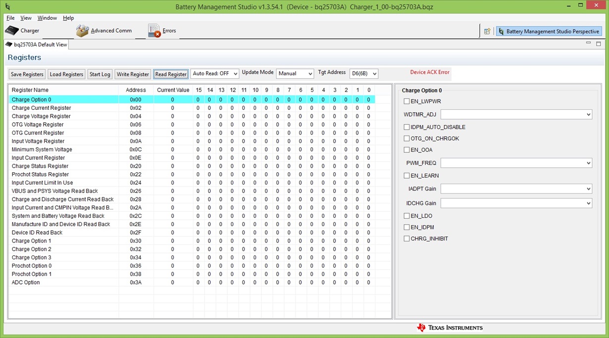
4. Screen shows DEVICE ACK Error

NB: When I plugged the EV2400 into my Windows 8.1 Pro computer, it showed up as a "USB Input Device" under the Human Interface Devices category of Device Manager.

Upon starting the bqStudio software, it says "Auto Detected Device : None", but gives no indication as to whether this means the software can't communicate with the EV2400, or the EV2400 target chip.
Is there any way to test if the bqStudio software can at least communicate with the EV2400?

  • Please make sure the connection between the EV2400 box and the EVM is through the port 2 of the box.
  • Update:
    There was an issue with the onboard 3.3V regulator, which I have worked around.

    After fixing this, the result of doing a manual register-read was initially the same, i.e. Device ACK error 

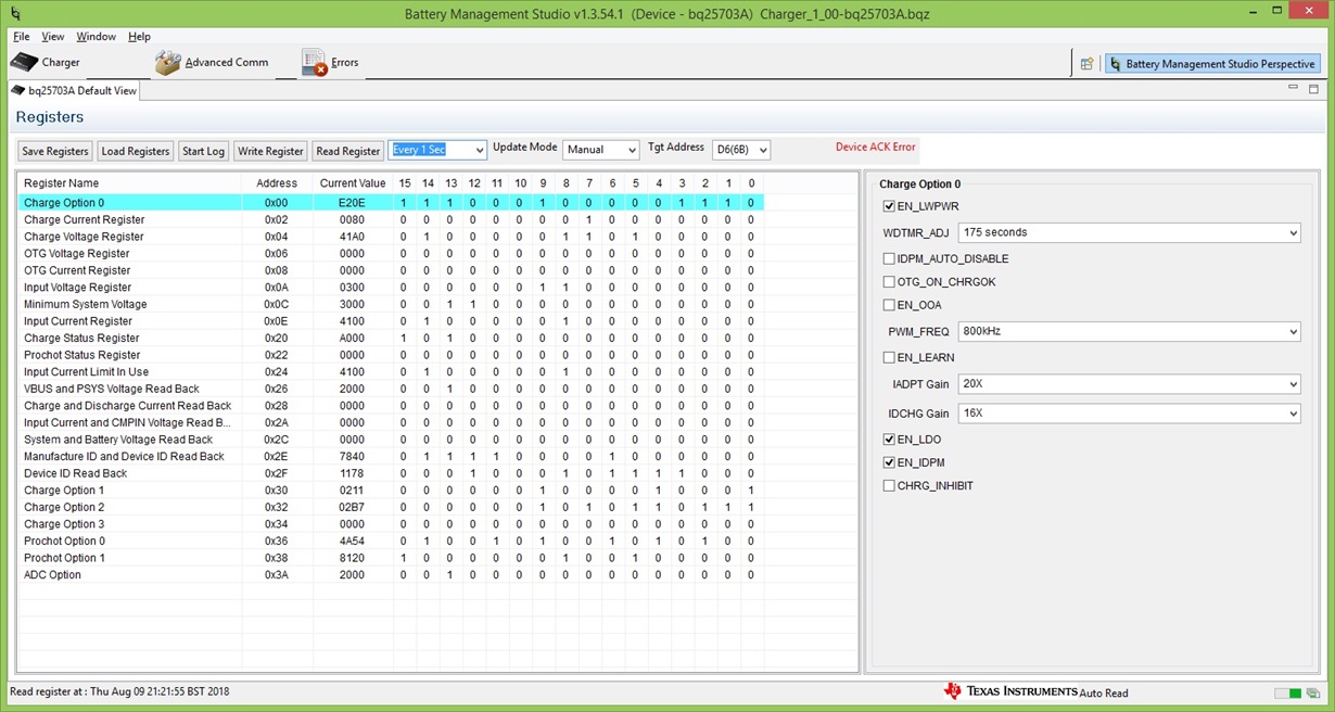
    However, by setting the interface to auto-read every second, then, after a while it would read first one then another of the registers until the "Current Value" column was eventually filled with numbers. This column took quite a while to fill, and I still see the Device ACK error on every read operation.

  • PS: You will note that the values read over I2C don't look right.
  • 1. "There was an issue with the onboard 3.3V regulator, which I have worked around."
    Do you see a 4.2V on 3.3V at LDO output? What work around do you do?
    2. Do you think the ACK error issue is related to the 3.3V regulator?
  • Curiously yes,I did see 4.2v on the regulator output. I assumed that meant the 3-pin regulator was broken, so my work-around was to remove it from the circuit and supply an external 3.3v supply instead.

    Was this a mistake?

    What made you ask about 4.2v specifically ?

    I'm not sure what the cause of the I2C issues are. I do have other I2C devices on the same bus, but that shouldn't affect anything.

  • The EV2400 box also provides a voltage source on the SMBus pull-up voltage which is connected to the on board 3.3V LDO output. That is why you could see a 4.2V if you connect EV2400 before the EVM power up. So, you can add EV2400 after the board power up to avoid this issue.

    Ok, I would think the ACK error message is not related to the LDO output according to your description.

    If you don't select "Auto Read: OFF" option and read register manually, do you still have "ACK error" issue?
  • Hi,
    I'm using I2C not SMBus. Does the EV2400 supply a 4.2V pullup with I2C as well?
    I still get ACK errors with manual reading.
  • Nicholas,

    Just to confirm, your thread title mentions the BQ25700AEVM, not the BQ25703AEVM. Can you confirm the IC on your board? Is it the BQ25700A or the BQ25703A?

    If it's the BQ25700A, it SMBus and there's both a different GUI to be used and different port on the EV2400. If it's the BQ25703A, then we can continue this investigation.


    Regards,
    Joel H
  • It is the BQ25703A, which uses I2C.
    It was not my intention to reference any other part.
  • 1. BQ25700AEVM-732 is different than BQ25703AEVM-732. The post title was BQ25700AEVM-732. So, we want to confirm you have BQ25703AEVM-732.

    2. According to your description, I don't think the issue is related to pull-up voltage. But, to confirm it. I want to know If you don't select "Auto Read: OFF" option and read register manually, do you still have "ACK error" issue? This can help us confirm: a. the board is BQ25703AEVM-732, not BQ25700AEVM-732. b. the issue may be related to "every 1 sec" option.

  • I repeat from my original message "I am testing charging operation using an exact copy of the BQ25703 EVM's example circuit, with EV2400."

    The circuit diagram from the BQ25703 EVM was included verbatim, as a section of a larger PCB design.

    The larger PCB includes other functionality, including other I2C chips.

    In a few days I should be able to get a storage scope hooked up to the I2C signals and check the levels and timing.

    I will also try replacing the 3.3 V regulator to see if that helps.

  • Hi,

    I have replaced the 3.3V regulator, and now I have a nicely regulated 3.3V rail.

    I have also hooked up the board to a storage scope, with I2C decoder capability.

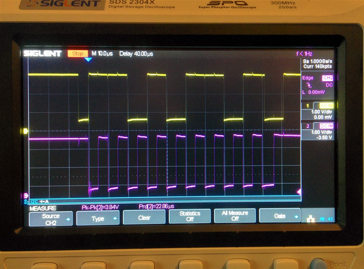
    Here is what the I2C signals look like when the EV2400 talks to the BQ25703 chip....

    The SDA on the PCB is the top (Yellow) signal, and the SCL is the lower (Magenta) signal.

    About one attempt in a hundred, the BQ25703 responds to the above communication from the EV2400, and the sequence is longer.

    Looking at the signal timing being produced by the EV2400, it doesn't seem to me to match what the BQ25703 datasheet says it should receive.
    What do you think?

    The datasheet says the SDA should be stable during the time when the SCL line goes high then low again.
    The SDA line can only change state when the SCL line is low.

    This is not what the scope seems to be showing.
    The scope seems to show SDA changing state simultaneously with the falling edge of the SCL.

    Is there a software setting that needs to be changed to make the timing of the signals from the EV2400 compatible with the BQ25703 ?

    Thanks

  • Hey Nicholas,

    The one thing I'm noting about your I2C waveform above is that the ground is offset; that seems incorrect.

    Is the ground of the EV2400 common with your board ground?


    Regards,
    Joel H
  • Dear Joel,

    Yes, the 4-pin cable from the EV2400 includes a ground conductor, which when plugged in, is connected to the PCB ground as per the reference schematic on page 13 of the following PDF for the bq25703 Evaluation Module. (See connector J3)

    http://www.ti.com/lit/ug/sluubg6/sluubg6.pdf

    The observed I2C signals SDA and SCL are normally HIGH at 3.0V, and are being pulled to within 0.5V of ground to indicate a LOW. (As shown on the oscilloscope screenshot I posted)

    i.e. If the SDA and SCL signals are supposed to go lower than 0.5V, then it can only be down to the EV2400 not pulling them LOW hard enough, rather than it being a ground reference difference.

    There is a possibility that my pull-up resistors on the SDA and SCL lines are too small in value, so the EV2400 can't pull the signals low enough. I will experiment to test this hypothesis.

  • Dear Joel,
    Sorry for the late reply.

    I replaced the 1k pull-up resistors on my PCB's SDA and SCL lines with 10K resistors, and now it works, and I can read and write registers with the EV2400.

    NB: I am aware that the EV2400 also has its own internal 20K pull-ups, but the PCB still needs its own pull-ups for when the I2C is controlled by my PCBs own micro-controller.

    Thank you.