This thread has been locked.

If you have a related question, please click the "Ask a related question" button in the top right corner. The newly created question will be automatically linked to this question.

bq40z50 - how to start

Other Parts Discussed in Thread: BQ40Z50, BQSTUDIO

Hi,

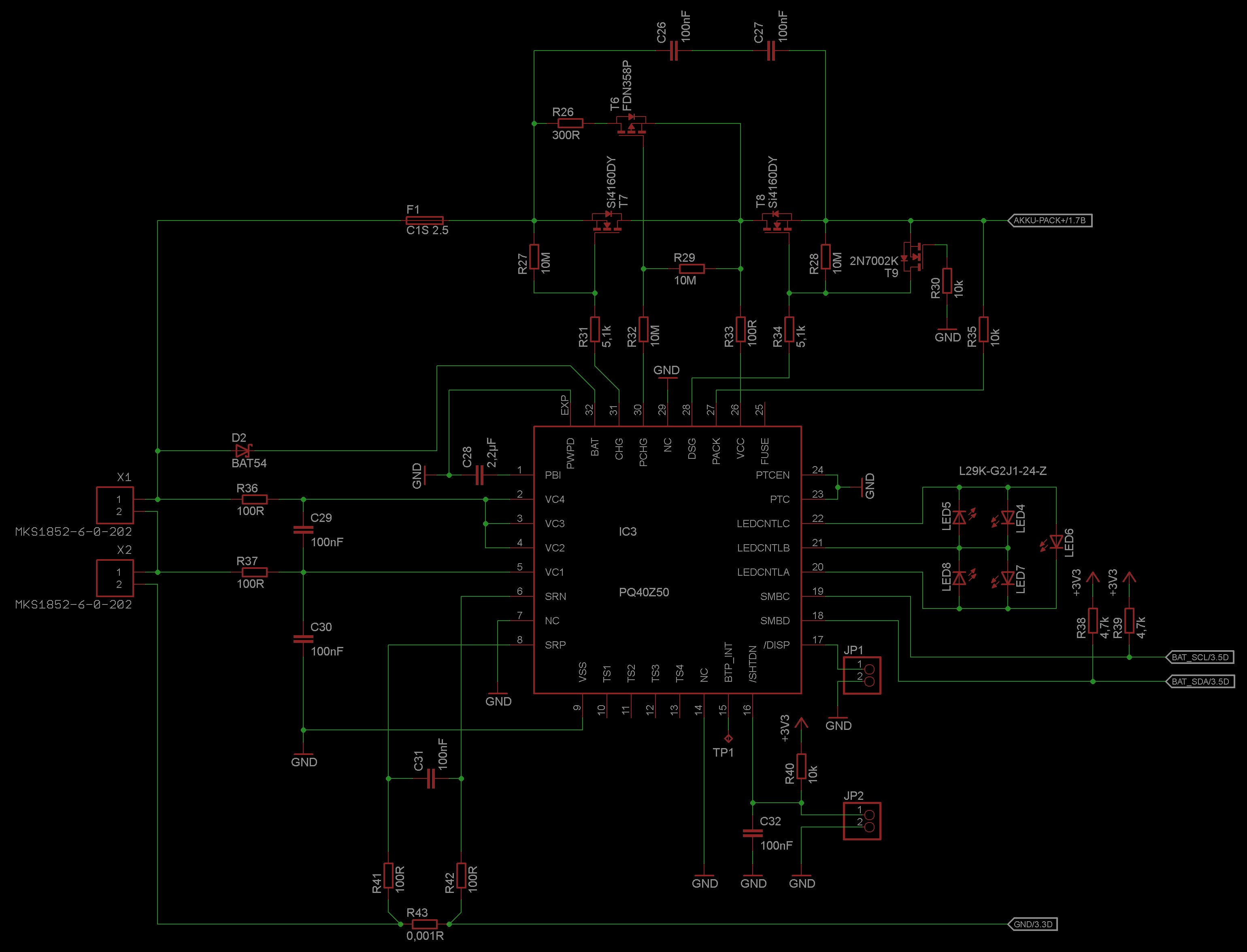
we will use the bq40z50 for an 2-Cell Li-Ion battery pack in an microcontroller driven device.

I've read the thread "Introduction to Multi-Cell Gas Gauges" on top of this forum and some other articles here.

Is it absolutly necessary to flash the device with bqStudio - or can i setup the parameters as an "initialization-sequence" from the microcontroller?

The default configuration for the bq40z50 i've seen is an 4-Cell-Pack.

Which minimum steps i have to do to configure the bq40z50 for an 2-Cell-Pack?

I've setted up the DesignVoltage() and DesignCapacity().

What i must do that i can charge and discharge the pack?

The IC goes to Sleep or something else after 5 Seconds - then it does not respond to any SMBus-Command. I toggled the LEDs on with "ManufacturerAccess() 0x002B LED TOGGLE" and they go off after this timeout.

Dirk

  • DIrk,

    The device is shipped with a default 3S configuration. Most of the parameters are cell based, but you do have to adjust the Design Voltage, Design Capacity (cWh) and the number of series cells in the DA Configuration register.

    You will need to turn the FETs on the charge or discharge the pack and you can do this by sending the FET Enable Command (22).

    It sounds like your pack is in Shutdown instead of Sleep. Do you have to apply the charging voltage to wake it up? If so, this would indicate that it is in Shutdown. Make sure that your number is series cells is set correctly and that the cells are above the Shutdown threshold voltage.

    I recommend configuring the device and running the optimization cycle using bqStudio. It will allow you to log data that will be very helpful to analyze problems that may occur.

    Tom

  • Hi Tom,

    i've missed the "DA Configuration" register. Now the Device stays ON. However the Pack-FETs are turned off. I tried the 0x0022 "FET Enable Command" but nothing happens. Neither discharging nor charging works. Also nothing happens when i set the /DISP-Pin - but when sending the LED Toggle command the LEDs go ON. /PRES (/SHUTDN) seems also to be ignored (default pulled to ground).

    After i unsuccessfully tried to install the EV2300 on my Workstation PC (Win XP, SP3) i get it to work on my Laptop (also XP 2002, SP3) with the Multilanguage-Drivers installed. I attached the Export File from bqStudio.

    I also changed the Temperature Enable Register to ignore TS1-4 (not connected) and use the internal Sensor. The PTC is also not used.

    Is there an diagram or something else where i can see when dis/charging is enabled and which conditions must be fulfilled?


    EDIT: The ChargingStatus[IN] Bit is set. But i'm not shure about this register because of the different description between TRM and bqstudio. TRM shows an 32Bit-Register (24Bits used) and bqStudio gives me 16 bits in different order.

    I checked the FET-Pins (CHG, PCHG, DSG) and toggle with 0x0022 command, but the pins stay still.

    Dirk

    2014-07-28_Backup_V001.gg.csv.zip
  • Is there an Wizard or calibration process in bqStudio where i can see what i have to do?


    Do the FETs turn on only in SEALED mode?

  • Dirk,

    There is a Calibration screen in bqStudio  and the bq40z50EVM User's Guide provides some guidance to calibrate the pack. You can turn the FETs on when the pack is unsealed. Use the FET Enable (22) command.

    Tom

  • Dear Tom,

    i tried to turn on the FETs using "FET Enable (22) command" - but nothing happens on the CHG, PCHG and DSG Pins - so the FETs don't turn on. The Charge Inhibit Flag is set in the Status register.

    Does the "FET Enable (22) command" ignore all other logic and turn the FETs on regardless of other settings?


    Dirk

  • Dirk,

    The FET Enable command just allows the FETs to turn on. They can turn off, if a protection event occurs. .

    Tom

  • Tom,


    after i reviewed the schematic i found an difference between the schematic from Evaluation Module and BOM "SLUUAV7–December 2013". The schematic has an value for R8 of 10MOhm, the BOM says 5k1 - which looks better.

    But this doesn't solve my problem, that the FETs won't turn ON. I disabled the FET-Control by Firmware with toggling FET_EN=0. Then i tried to toggle PCHG, CHG and DSG-FET - but nothing happens at the Outputs on the bq40z50 which should drive the gates.

    The device is already in unsealed mode, in OperationStatus low the "FUSE" bit is set. Is the FUSE-Pin only output or is it also an input for the 2nd level protection (which i did not use - see my schematic)

    Dirk

  • WTF... after my last post i checked the voltage at the FUSE-Pin (while the CHG_TEST and DSG_TEST Bits in the MfgStatus are 1) and then ... the circuit draws more current - it charges :-)

    The datasheet says first:

    FUSE  25  O  "Fuse drive output pin"

    but a few pages further: Figure 4. Pin Equivalent Diagram 2

    shows the FUSEDIG as an input. So i pulled it down with 100k and it works.

    Must i SEAL the pack that the FETs turn on and off automatically (without sending the FET-enable command)?

    Dirk

  • Dirk,

    The FUSE pin is dual purpose. It can drive the fuse FET after the bq40z50 declares a PF fault and it can sense that the 2nd Level Protector device has blown the fuse. You are correct that there is an error on the R8 in the schematic. The resistance should be 5.1 kohm, as shown in the BOM. I will update the documentation.

    Tom

  • Tom,

    after some minutes of charging i get an SafetyAlert[OC], and the Charge-FET turns off. I have read TRM P. 19:

    RemainingCapacity() ≥ FullChargeCapacity() AND Internal charge counter > 0

    So, my FullChargeCapacity is Zero and CycleCount = 0, DA Configuration[NR] = 1 - this should not happen.

    I read this thread: http://e2e.ti.com/support/power_management/battery_management/f/180/t/241902.aspx

    and enabled the Gas Gauge by setting ManufacturingStatus()[GAUGE_EN] and resetted the device with command 0x0041. But the FullChargeCapacity() remains at 0 mAh.

    What is wrong? The Voltage measured from the gauge is OK, the current shown is a little bit higher than it really is - but not significantly. The error happens after about 15 Minutes (not counted).

    Dirk

  • Dirk,

    I will need to check your setup. Can you save a log file showing the problem and export a senc file from the pack?

    Thanks

    Tom

  • Hi Tom,

    i'm not shure what you mean with an "senc file". I logged the time from charging until the Charge-FET was disabled and send you the log-file. I also send you the Device-Configuration (*.gg.csv - must zip it because the extension is not allowed...).

    The FET turns off while the Pack-Voltage is ca. 8000 mV, the Charge Controller however want to charge until 8400mV.

    Maybe i have to calibrate the shunt, but when i understand it right it should not stop charging because of OverCurrent for the first cycle (Cycle count = 0).

    I now have calibrated the shunt, and started a new charge cycle - will see what happens.

    Dirk

    bq40z50_OverCurrentAlert.zip
  • Dirk,

    It could be a calibration problem, but your gg file also shows that you are using the default ChemID 1210. Have you confirmed that this ChemID is a good fit for your cells? That can cause problems as well. You can export a srec file from the Firmware screen. (sorry that that I referred to it as a senc file earlier and this may have confused you)

    Tom

  • Tom,

    i attached you the Firmware. The chemical ID readed by Manufacturing command 0x0006 is 0x0100.

    I also updated the "chemistry in data flash" with bqstudio. I set it to "Panasonic CGR-18650C". Which parameters were updated by bqStudio while updateing chemistry? Is it only the chemical ID?

    The cells i use at the moment are Li-ion 18650C4.

    Another thing i noticed is, that when i power up the bq (first connect the cells, then apply charge current) the device does not answer on SMBus when my first query is too late (bqStudio says no ACK from device). When i'm fast enough the device stays powered on. I setted the NR(non removable bit) - but i got the same result when it was disabled.

    Dirk.

    2014-08-26_Firmware_readout.zip
  • Dirk

    I will review your srec file. ChemID 100 has been matched to the 18650C4 in the past, so that is a good starting point. The ChemID contains the OCV table, resistance tables and the disqualified voltage range and these are stored in the data flash.

    The default setting for the series cell count is 3S, so you will have to either connect the gauge to at least 3 series cells or apply a valid 3S voltage level to the Pack pin until you can switch the device over to 2S. It should work fine after you reset the device.

    Tom

  • Tom,
    i'm not shure if i understand it right: you wrote "The default setting for the series cell count is 3S".

    But i changed already the number of cells in the DA configuration register. But the device goes to sleep (or something else) when it starts-up and there is no communication on the SMBus. When bqStudio is attached to the SMBus it stays alive.

    Dirk

  • Dirk,

     I just wanted to make sure that had reprogrammed the device to 2S and were still having the problem. Are the SMBus signals high in the case where the device goes to Sleep? It should go to Sleep, if they are low. If bqStudio is not attached, then how do you know that it is in Sleep mode. One way to check for the Sleep mode state is to check the thermistor drive signal with an oscilloscope. It should pulse at a 1sec ot faster rate when in normal mode and it will pulse at a 20 second rate when in Sleep mode.


    Tom

  • Tom,

    i checked the levels on the i2c-bus and i noticed that they are pulled down from the EV2300 while bqStudio is not connected.

    So, i disconnected the EV2300 and the Pack starts up when i connect the supply (charger). I also checked the termistor line and it pulsed then every second.

    But when i only connect the cells (they are removable) then nothing happens until i connect the supply (apply charge current). Is it possible that the device starts-up only from battery? Trough the DSG-FET Body-Diode VCC is applied to the bq - so normally it can turn on both FETSs. Or is this prevented due to security?

    This scenario could happen when i change the batteries underway and have no power-supply.

    Dirk

  • Hi friends, please help me find the original SENC file for chip bq40z50. (Or SREC file.)

    My e-mail:   vvg@skyline.od.ua

  • Vladimir,

    I emailed the file to you earlier today, but here is another copy.

    Tom

    bq40z50_v0_12_build_24.srec
  • Dirk,

    That is not an option for the device. Voltage must be applied to the Pack pin, if it is in Shutdown.

    Tom

  • Tom,

    Thank you.

    Vladimir.

  • Is it possible that we get the OC Fault due to EMI or wrong board design? For example if we get an Peak in the current measurement path the OC Flag will be set?

    What are the conditions for the OC Fault?

    Next time we will order the BQ40Z50EVM and will try it again.

  • Dirk,

    Are you referring to an Over Current fault or an Overcharge fault? The [OC] flag refers to Over Charge. It will get set if the SOC reaches 100% and the pack continues to charge. The gauge will continue to count coulombs and the [OC] fault will get flagged after the coulomb count exceeds the Overcharge threshold. I would think that EMI would be more likely to cause an Over current fault. 

    Tom