This thread has been locked.

If you have a related question, please click the "Ask a related question" button in the top right corner. The newly created question will be automatically linked to this question.

Minimum number of cells supported by BQ76930

Other Parts Discussed in Thread: BQ76930, BQ76920, BQ78350

Hi,

1)  Can BQ76930 supports less than 6 cells ? If yes, what would be the cell connections for 5 and 4 cell series configuration.

2)The BQ76930 EVM shows usage of PFET in external cell balancing circuit. Is BQ76930 supports NFET in external cell balancing and let us know the connections.

Regards,

Vasanth M

  • The bq76930 supports only 10 down to 6 cells.  For 5 or 4 cells, use the bq76920 member of the family included in the same datasheet.  The power filter may be simpler and it can support more internal balance current than the bq76930. The register structure and general interfacing are the same. It also has a lower approximate price.  Since the package pitch is different you will need a different board for the bq76920.

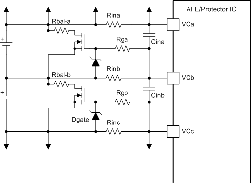
    Yes an N-ch external balance FET topology can be used and may have advantages. Basically mirror the balance components between the cell input resistors.  The gate protection zener of course needs to maintain the same polarity on the bottom side.  If your cell count is low enough and the Vgs of the FETs high enough, you may not need the gate resistors and protection zeners.

  • Follow-up question on the external balancing FET circuit - (nch or pch).  What case(s) does the zener protect against?  Presuming that a single Li cell cannot be above 4.5V and the Vgs max = +/-8V, why is the 5.6V zener required? 

    This is presuming only at most every other cell can be balanced (using bq78350 to manage which I presume enforces this).  The worst case I can find is Vgs = +-2.25V.

    Only case I can think of is if a cell opens - but in that case the battery pack is bad and it isn't important if the AFE gets damaged.

    We have a very tight layout and would like to eliminate extra components.

    Also, for external balancing - is there any requirement to keep balance load >= 100ohms as in the ref designs?  Any harm in a more aggressive balancing load (i.e. 50 or 27 ohms) as we have a large pack and are charging aggressively (2C-5C).  Yes, I have read the SLVA155 balancing app note.

    Thanks,

  • The zeners on the gates of the balance FETs and the gate resistor are for transient protection of the balance FETs. One of the events would be a short circuit.  Assume a P-channel balance FET on the bq76930 with 10 cells. Before short circuit the top cell and VC10 are at ~ 36V.  At the moment of the short, the top cell is now at ~0V while VC10 is still at ~36V, this voltage drops across the input filter resistor.  The resistor limits the discharge current of the filter capacitors.  Without the zener this voltage would appear across Vgs of the balance FET and damage it.  With the zener but without the gate resistor, the zener will conduct in the forward direction and protect the gate but would then discharge the filter caps fast with a high current. With both the zener and the larger value gate resistor, the zener will conduct, the current in the zener is limited by the gate resistor and the input filter does not discharge at a significantly higher current than without the external balance circuit.  A large gate resistor is desired to limit the additional current, in normal balance operation the zener does not conduct and gate current is small so the large value is OK. 

    When the short is disconnected, the cell voltages will return to normal very rapidly.  Now the cell voltage is ~36V or higher if there is an inductive transient from the cells while the input filter has fallen to some lower voltage.  If the input filter fell 10V, Vgs would be -10V.  The zener conducts in the zener direction to protect the gate-source limit and the gate resistor again limits zener current.

    If using N-channel balancing FETs the forward and zener conductions of the zener diode are reversed from the above description.

    Other transients can occur in the system which may be damaging to the FETs if the proteciton is not used or the FETs do not have sufficiently high ratings.  We did try to leave the protection off the bottom balance FET in a prototype board but that balance FET was easily damaged.

    Higher balance current is possible, this means more power dissipated on the board typically then with higher power and larger resistors or more resistors, both typically make the board larger or the balance circuit to occupy more of the board area.  The bq78350 will balance multiple cells at the same time but not adjacent cells in the same group. Remotely mounted balance resistors may be considered. A higher current can cause a higher voltage drop in any common path at the cell 5 connection or rather the cell that connects to the IC's cell 5, at the boundary between the 2 cell groups.  The common path resistance causes cell 6 to see a voltage shift when cell 5 balances for example since the groups operate on separate timelines.


  • Ok, thanks for the detailed explanation.  I would be temped to leave off the zeners on the bottom cells, but looks like you already tried that with not too encouraging results.

    Thanks again,

       - Peter