This thread has been locked.

If you have a related question, please click the "Ask a related question" button in the top right corner. The newly created question will be automatically linked to this question.

Blown BQ76940

Other Parts Discussed in Thread: BQ76940, BQSTUDIO, EV2400, BQ78350, BQ76940EVM, BQ76920EVM

Hi,

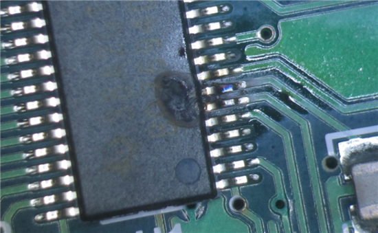
We are working with the BQ76940 EVM board and the BQ76940 chip on the board just blew. We are fairly confident that it is the LDO that burnt by looking at the image below. When measuring the resistance between BAT+ terminal and pin 7 on the BQ76940 chip, we now get a measurement of 7.7Ohm.

Here is our setup:
BQ76940 EVM
EV2400 connected to either I2C for BQ76940 Eval software or SMBus for BqStudio (ver. 1.3.18)
DC power supply adjustable from 0 to 64V with a current limit set to 2A.
Electronic load set to 1A.

The problems started when we followed the instructions starting on page 9 in the document SLVU925B and we reached step 15. We sent an email to Allen Y Chen to obtain a firmware for the BQ78350, but we had problems installing the firmware. The firmware updater would not recognize the device that was connected and it took several tries to succeed. After the firmware installation was complete, the LEDs (D48-D52) were lit up. The software (bqStudio) would still not recognize the eval board after resetting. The power was turned on for approximately 5 minutes before we saw smoke coming from the chip.

We had 48V set on the DC power supply with the current limit set to 2A. We had an electronic load connected to the PACK terminals (as shown in figure 2 in the document) but the load was not turned on. The voltage measurement on the PACK terminals was between 2.5V and 3.3V. When we turned on the electronic load for just a moment, the voltage would drop to 0V (we had it off when the chip burned).

The previous day, we had no problems. We were using a voltage of 30V and since we didn't have the firmware yet, we were limited to the instructions on page 8 for the AFE quick start. We had the same load connected and we observed the same behavior with the voltage drop when the load was turned on. The BQ76940 Eval software was able to detect the device when connected to the I2C connector with the EV2400

From what we described, is there any possible reason for the chip to burn like that?

Could the load have been turned on inadvertently and we would cause that problem?

Thank you in advance for your help.

  • Hello Michal,

    From the image, the discoloration of pins 6 TS1 and 7 Cap1, it looks like there was a short between the two pins.  

    • Cap1 is enables to the LEDs through a transistor and TS1 to c1 cell through the boot switch.  
    • When the LEDs were on  there was no short to ground at that time.  
    • Once the boot switch was pressed, this would have allowed a path from TS1 to Cap1.

    Check the state of SW1, the boot switch.  Also, remove what looks to be a bridge I between pins 6 and 7.

    Thanks,

  • I am using the development board (BQ76940EVM), so there is no bridge between pin 6 and 7. We checked with a microscope to confirm this. The discoloration is on pin 7 and we don't think there was a short between the two pins.

    And I'm not sure how pressing the boot button would cause this. The boot switch was not pressed when this happened.

  • Hello Michal,

    Those were just points to check to troubleshoot this fault on the hardware side.  The SW1 does not have to be pressed, it could be faulty.  That is also the only path to c1.  Since Cap1 is connected only to the base transistor, as far as I can tell from the schematic, you can do some more checks to see where Cap1 has a route to the positive terminal.

    Your next step would be to remove the chip and check the traces again.

    Thanks,

  • Note: I am going off of the bq76920EVM schematic.  The bq76940EVM Datasheet slvu925b crashes my browser when I got to the schematics section.  There could be some discrepancies in the design layout.

  • We have checked the board, the traces and the soldering and everything seems to be fine.

    We are still wondering what could have caused the problem.

  • A reversed polarity of the cell perhaps?  That is the only time I have seen this happen (one single cell chargers). 

  • Hi Greenja,

    Thanks for your efforts but it is most probably more complicated than a reverse polarity given all the details in the story above.

    The eval board is used with the batt simulator.  There is no bare cells.  Polarity can't reverse on a single simulated cell, let alone all the cells.  Anyhow, damages would have been immediate.

    TI experts are supporting us offline.  We'll make sure to post the solution once we have it.


    Frederic

  • Just to let everyone know, TI folks have been helping us offline on this one.

    It points to the EV2400.  Avoid using it to program the bq78350 until some update is available.

    Programming with EV2300 worked right away.  No smoke.

  • As noted the EV2400 does not program the firmware properly.  The result is the bq78350 draws excessive LED current overheating the LED dropping transistor causing it to fail.  This puts the battery voltage on the CAP1 pin exceeding its abs max and also feeds through the circuit and can exceed other pin's abs max.

    See the note on the EVM tool folders, use the EV2300 for programming at the present time