This thread has been locked.

If you have a related question, please click the "Ask a related question" button in the top right corner. The newly created question will be automatically linked to this question.

BQ20Z45 CUV alarm not clearing

Other Parts Discussed in Thread: BQ20Z40

I have a 2-cell application.  

CUV Threshold is set for the default 2200mV.  Cell 2 is at 3500mV.  I reduce the voltage on cell 1 until it drops below 2200mV - CUV flag is set, TDA is set, discharge FET goes off.  Great.

CUV Recovery is set for the default 3000mV.  Cell 2 is at 3500mV.  Now I raise the voltage on cell 1 back to 3100mV, above the recovery threshold.  But the alarm does not clear.  What is it waiting for?

Thanks

Ed K

  • Did you set an undervoltage PF flag as well ? Maybe it wants you to send the PF Clear Key ?

    Mike


  • Thanks - nope, no PF flags.  But I sent the clear key just for kicks, and no effect, the CUV is still up.

  • What if you raise cell 1 even higher than 3100 , does that make it work?

  • I will explain in detail what I just did and maybe you can tell me what happened.

    First I tried powering down and up, but the fault remained.

    It is a 3p2s configuration.  Cell 2 is an actual bank of cells, cell 1 is a power supply I am using so that I can vary the voltage.  

    I had the power supply at 3500, matching the actual cells.  It worked to set the flag, but not to clear it.

    I started thinking about impedances and maybe spoofing the chip was not working.  So I removed the cells and power supply and inserted a charged 3p2s set of cells.  Boom, flag was cleared.

    How should I be doing this test?

  • I am not sure what you did although I did toy with prevously asking you to double check the voltage on the inputs to the chip versus what you were presumably measuring at the cell in case there was any drop across the input resistors  but I thought no....... maybe I should have.  I brainstormed here and the only thing we can think of is you also have a charger attached to top of stack and were somehow asking the power supply on cell 1 to sink current as well, then it would not be happy as power supplies are generally not bi-directional.  The way round that is to put a contant current load box acoss the power supply output so that it can sink any current when you try to charge those terminals.

    Of course the more simpler way to exercise gauge settings is to simply use a stack of resistors, ie resistor ladder to simulate the cells then you can wind the voltage up and down as you like. Nominally 1K resistors are what I have strung across the cell inputs on all my evms. Of course you must rember to short any unused cells . You can even stick a supply and programmable current loadaround the sense resistor to make the gauge think it is seeing a charge or discharge current but for checking CUV  operation that is not required.

  • OK, I'm back on this project now.  I have been trying to get the CUV test done but can't solve this problem using resistors or pots or power supplies or batteries.  Let me take a step back.  I need to test all of the functions of the chip so is there a document somewhere that explains the best way to get that done?  I could pepper you with all kind of questions but if the info is out there I will look it over myself.

  • Figured out why the CUV does not clear.  The Z45 needs to see some charge current into the cell before it decides that the error condition has been cleared.  (I assume that is because the cell chemistry could allow the voltage to float up to the recovery setpoint without any charge current.)  

    We know you can't charge a power supply so that won't work.  Using resistors to simulate cells didn't work.  With a cell with a pot attached, the impedance is all wrong and it won't charge that way either.

    I used 2 cells in series and loaded cell one down with the e-load until it was 600mV under cell 2.  I then loaded the pack output until cell one dropped below CUV and tripped the alarm.  I watched the voltage float back up above recovery, but the alarm did not clear until I turned on the charger.  As soon as the Z45 saw the charge current the CUV flag cleared.

    So the tech ref manual and SLUA511B are only half right, the alarm clears when voltage goes above recovery, but how it happens is very important.

    I still don' t understand about " stick a supply and programmable current load around the sense resistor to make the gauge think it is seeing a charge or discharge current" - wouldn't that load down the power supply and not the pack?

    Any tricks about how to simulate charge overcurrent?

  • Hi Ed,

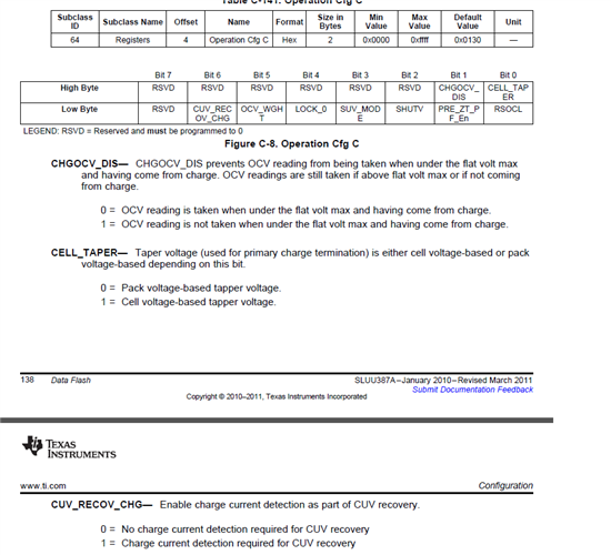
    I don't have the requirement to pass charge on my set up to recover from CUV but what you describe sounds like you must have the CUV_RECOV-CHG bit set  in the Operation CFG C register?

    but this is not the default setting so I guess it must have selected intentionally by someone ?


    My board works quite happily with the resistor ladder and I can clear CUV just by raising voltage across resistor ladder,  so maybe try clearig that bit unless you would like to keep that feature.

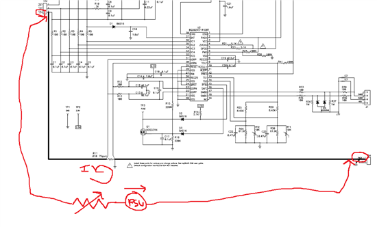
    the objective of the power supply and electronic load connected around the sense resistor is to just pass current through the sense resistor and not through the power supply biasing up the stack.  So connect your supply and load across the Pack -  and 1N terminal so that the current only flows along the gnd line through the sense resistor. You will have to change the orientation of the connections to suit the current direction you want to simulate charge or discharging

    Mike

  • CUV_RECOV_CHG is set in Op Config C.  How it got there I don't know.  I didn't set it.  Clearing it allows the CUV alarm to clear as you say.

    The doc I have been using for flash configuration is SLUA511B, Configuring the bq20z40/bq20z45 Data Flash, Revised November 2013.  In that document bit 6 of register Op Config C is left blank, there is NO DOCUMENTATION for CUV_RECOV_CHG (see page 53).  From now on I will double-check it with the TRM.

    Lastly, on the Z45 the sense resistor terminals are labeled PSRN and ASRN.  When you say 1N do you mean ASRN?  Because when I hook it up like that I can dial the current in just fine  : )

    Thanks for all your help  on this.

  • I attached a sketch. yes the sense resistor goes to ASRN and ASRP ( but is actually sensed for measurement by GSRN and GSRP), so Pack- is effectively connected to ASRN , and the 1N terminal which is ground of the lowest cell on EVM connects to ASRP. So If you attach a series supply and current limiting load across these points you can flow a current in either direction through the sense resistor to create different test charg/discharge current.