This thread has been locked.

If you have a related question, please click the "Ask a related question" button in the top right corner. The newly created question will be automatically linked to this question.

BQ40Z60EVM - Adapter power only

Other Parts Discussed in Thread: BQ40Z60

Is it possible to drive a load with only AC adapter power and no battery connected with the bq40z60 Evaluation Module circuit?  If so, what are the configurations/settings required?

  • The bq40z60 was not designed to run off of the charger without the cells attached. You can have some level of functionality, but you cannot use gauging and you will encounter faults.
  • Tom,

    Can the BQ40Z60 run a load when the battery is fully discharged?  The EVM uses a pushbutton to apply temporary power to 4P, but our application does not have this button.  An OLED display and micro is powered from the BQ40Z60, and currently, the only way I can get power to that circuit is to temporarily apply a positive voltage to the BAT circuit.  How can this be done without human interaction?  Is there a setting that will allow the system load to run from the adaptor?

  • I am using a couple power path controllers (LTC4412) to drive the load only from the AC adapter when it is present. This bypasses the bq40z60 circuit and allows the system to operate if the battery is removed or a fault prevents the battery from discharging.
  • Jim,
    Are you seeing that the charger is not turning on when the adapter voltage is applied? The bq40z60 should wake-up when the charger voltage is applied and it will run off of the VCC voltage until the BAT voltage goes above the switchover threshold. If the battery voltage is below the level at which the system can operate, then you can add a pre-charge FET and resistor to charge the batteries without pulling the system voltage down to the battery stack voltage. Reference the bq40z60EVM schematic for the pre-charge implementation.
    Tom
  • The BQ40Z60 does indeed power up, and I am able to communicate to it using the Battery Management Studio, but it does not seem to enable ACFET and/or HIDRV/LODRV to bring adaptor power out to the SystemLoad.
  • Jim

    Was the CHARGER_EN set before the adapter voltage was applied? Also, what is the battery stack voltage when you are trying this experiment? I can try it on my bench. 

    Tom

  • Hi Tom,

    Yes I do have CHARGER_EN set. I'm using BTP settings.

    I can get system load voltage when I set NR from 1 to 0.

    I have .55V on the gate of Q8 (EVM schematic), and zero on the gate of Q9. When I change NR from 1 to 0, the gate of Q8 jumps to ~10V and the gate of Q9 rises to .4V. Both charge and discharge FETs are off (XCHG and XDSG = 1). XDSG is typically 1 due to CUV and CUVC, but no low voltages affect the CHG FET, only over voltages and NR being set to 0.

    I would think that once ACP and VCC have the proper voltages, HIDRV/LODRV, ACFET and others should be active and provide system load power.

    - Jim
  • Jim

    I am able to power the system with the charger when the battery is low. Can you send an srec from you pack? It is probably a configuration problem.

    Tom

  • Hi Tom,

    I think I may have a way to handle this scenario using PF OPENCELL, of which I can clear after the MCU get powered.  Once a PF is triggered, XCHG = 1, and the Buck circuit becomes active providing power to the load.

    I have another question related to AC Adaptor Power circuit.  Referring to the EVM schematic; after removing power from the VAC circuit, that circuit still maintains a voltage above VSYS, which prevents the ACFET from turning off.  If I discharge that circuit to ground, ACFET will disengage.  Is there a setting somewhere that can be adjusted to resolve this issue?  I have the same problem on a prototype board.

    Thanks,

    - Jim

  • Tom,

    I should have looked deeper into my last question prior to asking it, my calibration was off.

    I appreciate your assistance with my other inquiry, but if you know of a different way to have both XCHG and XDSG = 1 other than using PF that would be great.

    Thanks,

    - Jim

  • Thanks Charlie, I'll keep this in mind. The project I'm working right now has very limited space, so I'm working on more of an inherent solution.

    - Jim
  • Hi Tom,

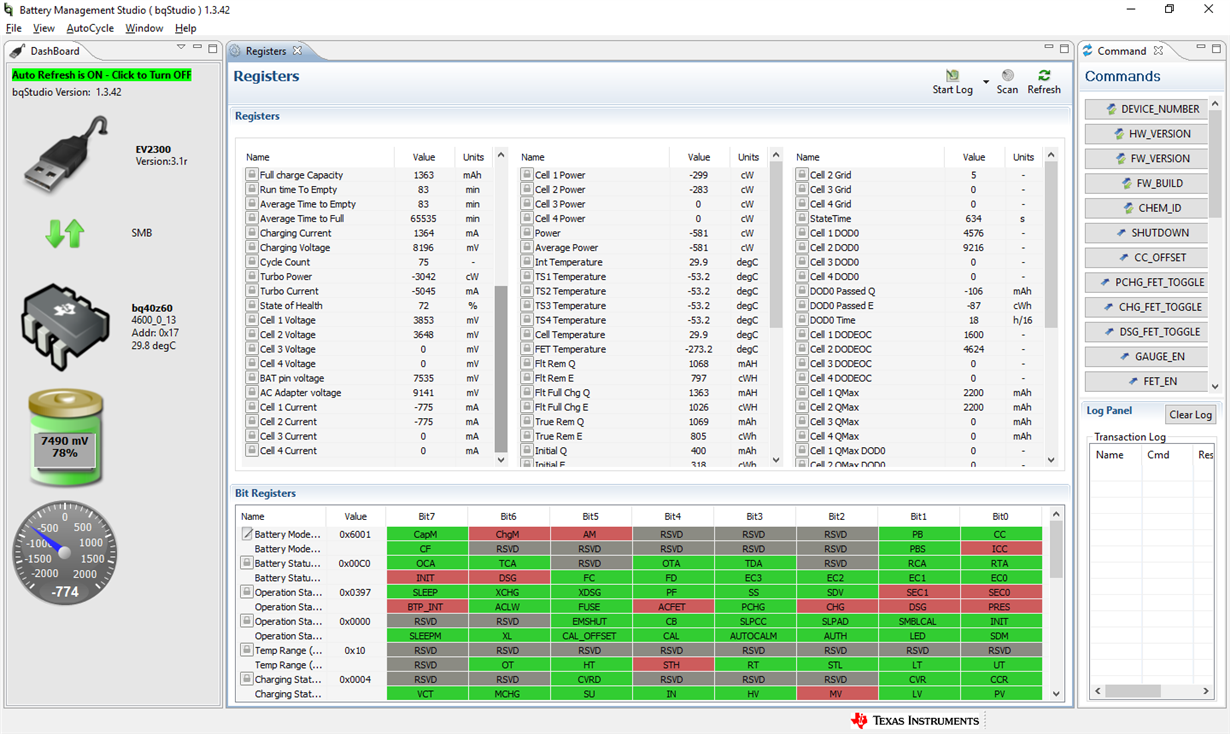
    I actually thought I had a resolution, but I still end up with voltage shown on the "AC Adaptor when the charger is removed;  I cannot get ACFET to turn off after removing charger voltage.  Here is a screen shot.  My charger voltage is actually 12.5V

  • I may have confused things a little. The screen shot is AFTER the charger has been disconnected.
  • Jim
    I still have not been able to reproduce this behavior on the bench. Can you send an srec file from your pack? I will send a private message to get the unseal codes.

    Tom
  • Tom,
    You said "you will encounter faults"... What kind of faults? The evaluation board coherently works without cells attached; instead my custom board doesn't, because the charger doesn't turn on when the adapter voltage is applied. I had tested the evaluation board, and I was sure that my board would work without cells to. When I've tested my prototype board, charge e discharge worked well, so I thought it was all ok. Then, I've mounted several boards, but they don't work! I have to throw them in the trash? Or is there some way to fix them?
  • Pietro, what we did to handle the adaptor only scenario was that we added a diode OR-ing circuit to power our micro when batteries were not connected. The problem we ran into was that the BAT line needed a voltage in order to power up the BQ40. So we had some choices to make, either add more components to the charger board to give a short pulse to the BAT line to accommodate this, or add a single component to the micro PCB; we choose the latter. We needed to add a small mosfet RC timing circuit to the charger board to power up the charger when batteries were connected without the charger. This circuit applied voltage to the ACP line just long enough for the BQ40 to power on.
  • Jim,

    Certainly, what you say it is correct. However, why does the evaluation board also work without batteries? Why does the charger of the evaluation board start with adapter only ? Why doesn't mine do?

    The only difference, that I can see between boards, without batteries, is that the voltage on the BAT line, in the evaluation board, remains fixed to GND, instead, in mine, it floats upping with the load current until the bq40 power supply switches to BAT and, since there isn’t a real voltage source on BAT, then it powers down.

    Regards

  • Pietro
    The device was not designed to work without cells. It should power up, but you may have issues with running the charger. BAT is the primary power source for the device and it will run off of VCC, if BAT is not present. Please provide your schematic and I will try to find out why your BAT voltage is increasing.
    Tom