This thread has been locked.

If you have a related question, please click the "Ask a related question" button in the top right corner. The newly created question will be automatically linked to this question.

Problem with Setting the IT Command

Other Parts Discussed in Thread: BQ34Z110, BQ34Z100-G1, BQSTUDIO, BQEVSW, BQ34Z100

Hi All

I have problems with getting the learning curve done on a BQ34Z110 and on BQ34Z100G1

I am sending the Command from The I2C write Byte as follows

Command 00 then 00 as byte

then command 01 and 21 as byte

this the whole sequence looks as this Control commnad 0x00 and byte 0x00 mControl command 0x01 and byte 0x21

= 00,01,0021

however I never see the VOK or QEN bits get set as the datasheet mentions

what am i doing wrong as i expect the device never learns or update the Ra tables

also I see the RUP_Dis bit is laways set does this mean that updating the tables are diablled how do I clear the bit RUP_dis ?


many thanks for the help

Best Regards

  • Peter

    Try using the Control field on the DataRAM screen. Enter 21 and press the <enter> key. You can also try the Write I2C Data Block field on the I2C Pro screen. Enter the data as this:  I2C Command 00   Data Block 2100 and press Write Data button.

    Tom

  • Hi Tom Thank you very much I will try this Have a gret weekend Peter
  • Hi Tom

    Thank you I  managed to set the IT command with a Block write,

    I have a small misunderstand ,when I have send the IT command the VOK and QEN bits set as mentioned in the datasheet and the RUP_dis bit cleared which in my understanding means allowing the device to update the RA tables ,All when well until around 15-20% discharged then the RUP_dis bit was set again to 1 is this normal or should the RUP_dis bit stay cleared until the nendof the learning curve ?

    The VOK and QEN bits dis not change at all,I am not sure now if the device is learning or not  :) 

    Best Regards 

    Peter

  • The gauge ignores the RUP_DIS flag until Update Status = 06, so that is okay. This is a common occurrence until Qmax and the Ra table have updated.

  • We do not have a device that can support balancing PbA cells, but most PbA batteries are built in 6S configurations where the internal cells are not accessible. They could not be actively balanced anyway. Cell imbalance will affect performance, but the gauge will do the best that it can to gauge the pack.
  • Hallo Tom

    Thank you for the answers it does help a .

    Cell Balancing is of no importance with me ,it  is only a factor with my US colleagues ,I need SOC and Run time to empty if it is with in 5% I will be home and dry 

    However I ran into an issue with the learning curve I will make another post once I have all the facts together and ask then for your expertise .

    Have nice weekend appreciate all your help 

    Regards 

    Peter

  • Hi   Tom 

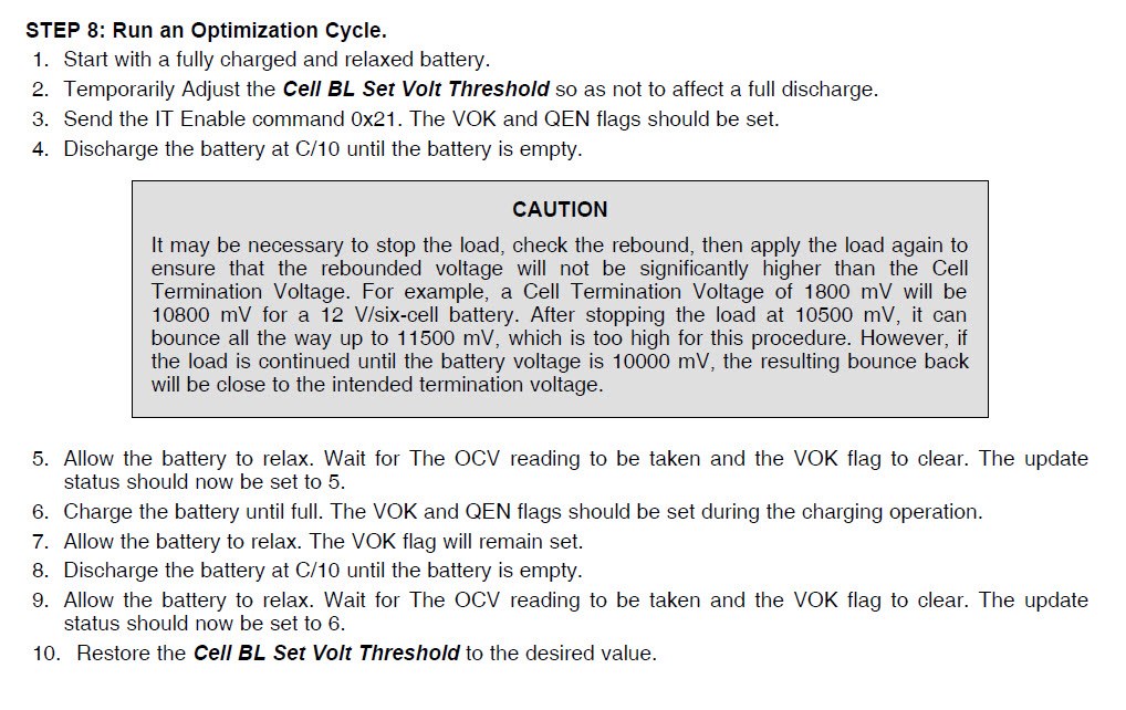
    I have completed steps 1 -5 in the Design steps Number 8 Running the optimization cycle ,

    it seems that the device is stuck at doing the VOK measurement  it was already 2 hours in Relaxation mode and the OCV_Taken Flag is set however the VOK bit does not clear and the update status remains in 0x04 .

    (1)is this supposed to happen automatically or do I need to do something as my understanding from the attached section from the datasheet it seems that the device should do this automatically .which it does not do what could cause this ?

    Regards

    Peter

  • That probably means that the change in DOD was not sufficient to qualify for a Qmax update. Are you using the bq34z100-G1 or the bq34z110? We changed some internal parameters on the bq34z100-G1 to make it easier for the Qmax update to qualify. The problem is that the cell voltages increase a lot during the rest after discharge. They may rest back up to close to 50% DOD and the bq34z110 is setup to require a 90% change in DOD for a Qmax udpate. The bq34z100-G1 requires a 50% change in DOD. If you are using the z110, then you can use the attached senc file and the default parameters have been updated to match the -G1 parameters.

    8176.bq34z110_V0_04_modified2.senc

  • Tom 

    Thank you very much for the help and the updated senc file ,yes I am using the z110 as I have all the communication I2C protocol from the work I did for the US team 2 years ago and I have hardware which is layout out for this specific vehicle , 

    I will give the new file ago and if no luck then I possibly should move on to the 100 G1 ,did any communication commnads or data adresses changed in the

    z100G1  ,Can I just program the z110 with the z100G1 firmware as i do not have z100G1 devices and to get then could take a few days or weeks which I do not have the time for

    Regards

    Peter 

  • Peter,
    You can program the -G1 firmware into your existing device using bqStudio. There are a few parameter / commands changes with the -G1 device. We tried to minimize the changes to make it easier to convert to the new device.
    Tom
  • Hi Tom

    Thank you I am starting to consider this option ,I am just trying to avoid redoing all the I2C code which I have , this is all  for a proto type vehicle my collogues  design in the US  is going into production now in 2016 model year .

    I tried the new file today again the VOK bit does not clear and the device does not move into update status 0x05,

    Just checking with you if I am working in a correct steps 

    (1) I have a pack which is fully charged and relaxed 

    (2) I have no precise Qmax value so i entered in Qmax Cell 0 the same value as in the Design capacity which is 10 000 mAh (4 batteries in series 100Ah rating and  Config is set at x10 mode)

    (3) send IT enable command Command 00 and 2100 data ,VOK and QEN bits get set 

    Then I discharge the pack at C10 well below the cell cut-off voltage (1.5V /cell = 36V pack voltage) the bounce back voltage was at 34.8 and then slowly rized 

    to 38.9 in about 1 hour 

    The OCVTaken flag did not set the VOK did not clear and the status remains at 0x04 

    Could this be that I have to do some learning of the Qmax value as I am not sure if the device can determine the Qmax value ???

    I appologise for all this I was hopeing by now I would have the device in status 6  and the Ra tables are updates but no go so far 

    Best regards 

    peter

  • Peter,

    Your process looks correct. Could you send the log file and export a senc file or srec file from the gauge and send it as well. I will try to fix it for you?
    Tom

  • Tom 

    I have now setup my EVM module I will do the same test and also log the data if the same problem occurs I will forward the files to you 

    thank you very much for your help

    Peter

  • Hallo Tom

    I fail to see how to export asenc file from the device with the EVM software? 

    I have used the EVM module and started to do the learning curve as you will see in the attached screen prints the following happens

    • Discharged the battery pack at C10 and the VOK bit cleared the OCV_taken bit set as the leaning curve process describes however the update status remained at 0x04 this is my confusion as the Control status showed 0x05 Does this mean the device is in the correct state now 
    • I then though let me just go to the next step and charge the batteries and again as the learning curve describes the VOK bit got set 
    • This seems that the device is going through the learning process however the update status does not reflect this .

    does this seems to be correct or is the device not learning ,how do I export a senc file I can only export .gg file , I alos attach the log file and the current ggc file 

    Regards 

    Peter

    2235.Leoch_120AH_learning curve.log

    SA BMC Setup and Tests.doc

  • Peter,
    Your process looks correct and the log data indicates that Qmax and Update Status should have updated. I would check the Flash Update OK Cell Voltage to make sure that it is not too high. The flash will not update if the cell voltage is lower than this value. You can send a senc file and I can check it. You can export a senc file from the I2C Pro screen. Place the gauge in ROM mode and then use the field at the bottom of the screen to save the file.

    Tom
  • Hi Tom 

    Please see attached senc file 

    In this file I did the initial discharge cycle then a charge cycle and again the discharge cycle however the update state is still at 0x04 ,

    Thank you I will check the Flash update cell voltage OK and will appreciate if you can check this in the senc file too.

    I see 1800mV with me however with this large battery pack possibly I can set this value much lower around 1000mV what would be your guess 

    SA_BMC_01.zip

    Peter

  • Peter,

    the Flash Update OK Voltage was set too high. I analyzed you data with a Mathcad program and found that ChemID 807 is not a good match to the latest log file. ChemID 804 should work okay. I updated the ChemID, Ra table, Qmax and Flash Update Voltage, so you should not have to run the optimization cycle again. The current calibration data was corrupt in the senc file that you sent, so I arbitrarily set it to 10.

    • Load the attached senc file.
    • Calibrate the pack.
    • Send the IT Enable command.
    • Run some cycles to check gauging performance.

    Tom

    SA_BMC_01 modifiedTI.senc

  • Tom

    Thank you very much,I appreciate your efforts and help.

    I will do as you mentioned .

    Peter

  • Hi Tom

    ---------------------------------------------------------------------------------------------------------------------

    Tom wrote:

    The current calibration data was corrupt in the senc file that you sent,

    --------------------------------------------------------------------------------------------------------------------

    I did the calibration with the EVM evaluation software in the Calibration window,I am worried that this calibration data was corrupted,

    The new file  you send me seems to work quite well ,we will run a few more cycles to check next week,I did the calibration again with the EVM software and 

    hope I do not have corrupted data again as the current measurement is slightly out and the board off set seems not to calibrate as i do not achieve 0 amp when no current are flowing is there no way to calibrate the shunt by hand as it seems the slope of the curve is wrong (Y= mx+c) 

    Thank you once again for all your help you really helped me out of a difficult situation 

    Regards 

    Peter

  • Peter,

    There is a board offset calibration issue with the bqEVSW. It has been fixed on the bq34z100-G1 and bqStudio. You can try changing the sign Board Offset parameter in the data flash (multiply it by -1) to see if this helps. Otherwise, I would set the parameter to 0 and try recalibrating the coulomb counter and full scale current. 

    Tom

  • Tom

    Thank you very much ,I will do this on Monday ,
    as we have ons system running now that allows for the application people to drive the vehicle i will start to work on moving over to the BQ34Z100 G1

    Have nice weekend
    Peter
  • Hi Tom

    I managed to program the BQ34Z110 with the Standard srec file supplied with Bqstudio and I can communicate with BqStudio all seems to work well although I have to adapt my I2C code.
    just a question I have the senc file you modified for me for my battery pack could this file be used now for the new BQ34100 G1
    as it seems that Bqstudio you can only program srec files
    you help is appreciated as always

  • Peter,
    The bqStudio program does not support senc files. The parameter set has the updates that I made to the "modofoed" senc file that I sent for the z110. We do not have a tool to import a z110 setup into the -G1 device, so data flash parameters have to be updated by hand. You can then save a gg.csv file or .srec file to import into other devices. One note on the gg.csv file is that you must edit it with a text editor. The file will no longer be usable, if you update it with Excel.
    Tom
  • Tom

    Thank you very much ,I will do it by hand and run a cycle to get the update status too 0x06

    Appreciate this
  • Hi Tom

    I have been running the BQ34Z110 with the file you helped me with and it worked well 

    However I have seen a problem today which I need you to help me understand 

    the battery pack were down to 65% we charged the pack SoC went to 100% and Remaining Capacity to its normal 12127 then on a road test the Soc did not go down the pack were nearly completely run down I then used the EVM software the TDD bit was set and the IS bit not 

    It seems from the datasheet TDD means Tab disconnected what is is this tab mean and could this result in the SOC getting stuck ?? and what could cause this will help me track the problem down

    Looking forward to your reply 

    Regards

  • Hi Guys

    I am not sure if my last post has been seen by anyone however

    I really need to understand the function of the TDD bit as I have a unit that would count down the remaining capacity  on discharge and then the TDD bit gets set and the Bq device seems to lock up I can completely discharge the pack but the SoC stay at the value it got locked at anything between 100 and 96% 

    Regards

  • Peter,
    The TDD is the Tab Disconnect feature that detects whether there is a flaky cell connection. Having the bit set should not cause the gauge to stop working, but maybe there is a connection problem, the voltage dropped out and the gauge did not recover. I would check the cell connections. We removed this feature and the ISD feature from the bq34z100-G1 to free up space for code improvements and also because these features have caused false faults for some customers.

    Tom
  • Tom

    Thanks a million I understand I will check the pack connections ,I am certain the gauge stop to count down ,
    any other cause you might think of why the gauge would stop to work it like a hanging micro controller
    I am progressing with the Bq43z100 G1 however i need the vehicle to run while I am working on the 34z11