This thread has been locked.

If you have a related question, please click the "Ask a related question" button in the top right corner. The newly created question will be automatically linked to this question.

BQ34Z110: Impedance Track: determining SOH without relax time?

Part Number: BQ34Z110
Other Parts Discussed in Thread: BQ40Z50, BQ40Z50-R2,

I was looking at a 2015 seminar about the impedance track algorithm.

One of the topics is "no relaxation applications", however the speaker ran out of time and skipped the relevant slides. I was unable to find the slides online. Only the 2017 versions are online and they do not contain any information about this topic as far as I can tell.

Are these slides available somewhere or could someone explain to me if it is at all possible to determine SOH without relaxation times?

  • Hi Sammy,

    It's a shame the speaker ran out of time and skipped over those slides! The resolution to the 'no relaxation' problem is pretty interesting. We call it 'Fast Qmax'.

    Please refer to the Day_2_Gauge_Multi-Cell_Gaugin for Industrial Applications_bq40z50_R2.pdf from the 2017 Deep Dive. On Slide 4, entitled, "Relaxation conditions difficult" where this topic was broached.

    In short, some gauges, such as the bq40z50-R2, have a feature called Fast Qmax. If the cell is not relaxed, a straight OCV measurement cannot be taken. Without two OCV measurements taken at sufficiently spread depths of discharge (DOD), accurate Qmax for the cell may not be calculated.

    However, with Fast Qmax, DOD@EOC is utilized to estimate the DOD at the end of charge for the cell. So, if your pack is discharged close to empty (either before or after a full charge where FC was set), Fast Qmax will utilize DOD@EOC, improving gauge accuracy without relaxation.

    That being said, relaxed OCV readings (taken at relaxation) provide better accuracy.

    Sincerely,
    Bryan Kahler

  • Hello Bryan,

    Thanks for your response. Very interesting, though our fuel gauge does not seem to have this feature.

    You mention the importance of two measurements at different DODs.

    Our system is used in such a way that it is either plugged in to mains (=charging) or is being used in portable mode (=discharging). It will generally never be left in a state where it is not charging or discharging, except at full charge.

    As it stands we were hoping to use the point at which the system is plugged in and the battery is fully charged as our relax period. However, if I understand correctly this would lead to a very innacurate Qmax because the point of measurement is always at the same DOD?

    We can probably change our charging algorithm to put the battery in relax for a few minutes at certain intervals of SOC, but while discharging this is obviously not an option.

    Are there any other guidelines regarding the relax periods? How often do these need to occur and for how long? We're using a 12V/40Ah lead acid battery.

  • Hi Sammy,

    I didn't mean to sound all doom and gloom - there is hope still!

    One of the OCV measurements will be taken care of by your relax at full charge.

    You can pick up your other OCV measurements when the gauge has entered relax mode (when average current is below quit current). After ~6 minutes in RELAX mode, with current below C/20 and a small average voltage delta, dV/dt < ~4uV/s, a reading will be taken (assuming a large enough depth of discharge has occured).

    You can monitor OCVTAKEN to see if it sets with your normal load profiles as well as QMAX0 for updates.

    Sincerely,
    Bryan Kahler
  • Hi Bryan,

    What do you mean exactly by picking up other OCV measurements after a while in relax mode? As it stands there is only one "point" at which the battery will be in relax mode (i.e. at full charge). So basically all OCV measurements will be taken at the same point.

    We'll probably have to modify the code to take several measurements during charging. The OCVTAKEN and QMAX0 flags will be very useful for this.

    Kind regards,

    Sammy
  • Hi Sammy,

    I apologize for the delay in response - my first pass reading this post I missed the question.

    The battery is able to relax when the load is removed, or is very slight, allowing the open circuit voltage to be measured.

    Sincerely,
    Bryan Kahler

  • Hello Bryan,

    We have done some extensive testing in order to determine if and when the BQ34Z110 performs QMAX updates. Right now we have a test running where the battery is cycling between charge and discharge.

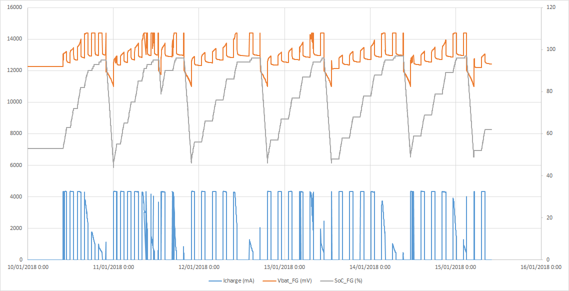
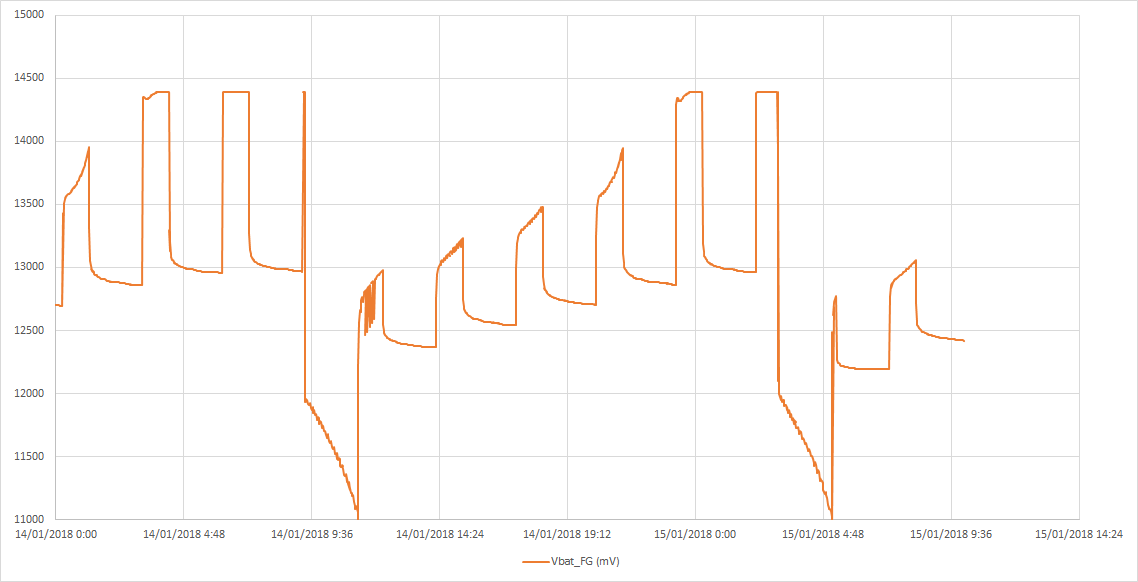
    During the charging step we added a periodic cutoff from the battery where the charging is stopped and the battery voltage is allowed to relax. The current parameters are: 1 hour charge, 2 hour cutoff. This is visible on the following plot:

    However, we see that the battery voltage is still stabilizing even after 2 hours.

    The parameters for the fuel gauge are as follows:

    [Current Thresholds(Gas Gauging)]

    Dsg Current Threshold = 20mA

    Chg Current Threshold = 25mA

    Quit Current = 13mA

    Dsg Relax Time = 60s

    Chg Relax Time = 60s

    Quit Relax Time = 1s

    Cell Max IR Correct = 400mV

    We're also monitoring the various registers and logging every change in the fuel gauge flags and FCC. From this we can see that FCC changes very minimally and the fuel gauge flags indicate that OCVTAKEN bit is always low so an OCV measurement is never performed.

    I assume this has something to do with the requirement that dV/dt < 4 μV/s for the BQ34Z110 to perform a QMAX update, but this is something we can not change.

    I don't see how we are supposed to ever take OCV measurements in a practical way. Are we doing something wrong or is this normal?

    Kind regards,


    Sammy

  • Hi Sammy,

    Thank you for this clear image and description.  

    For a Qmax update, OCVTAKEN should assert when the battery relaxes and and OCV value is measured with enough DOD between two OCV measurements.  In the above image, I do not see the battery relaxing at different depths of discharge, a requirement for a QMAX update.

    Please attach your log and your gg.csv file so I may analyze your settings and corresponding results.

    Sincerely,

    Bryan Kahler

  • Bryan,

    Thanks for your help. I have attached the gg file we use (I've changed it to txt extension as the forum wouldn't let me post a .gg file).

    default.txt
    [Header]
    bq EVSW Version = 0.9.90	
    DeviceName = bq34z110 v0.04
    Time = 26/09/2017 12:21:57	
    
    
    [Safety(Configuration)]
    OT Chg = 55.0
    OT Chg Time = 2
    OT Chg Recovery = 50.0
    OT Dsg = 60.0
    OT Dsg Time = 2
    OT Dsg Recovery = 55.0
    [Charge Inhibit Cfg(Configuration)]
    Chg Inhibit Temp Low = 0.0
    Chg Inhibit Temp High = 45.0
    Temp Hys = 5.0
    [Charge(Configuration)]
    Suspend Low Temp = -5.0
    Suspend High Temp = 55.0
    Chg Eff = 100
    Chg Eff Temp Comp = 25
    Chg Eff Drop Off % = 96
    Chg Eff Reduction Rate = 10
    Maintenance Current = 0
    [Charge Termination(Configuration)]
    Taper Current = 133
    Min Taper Capacity = 25
    Cell Taper Voltage = 100
    Current Taper Window = 40
    TCA Set % = 99
    TCA Clear % = 95
    FC Set % = 100
    FC Clear % = 98
    DODatEOC Delta T = 10.0
    [Data(Configuration)]
    Rem Cap Alarm = 100
    Design Cell Voltage = 2000
    Initial Standby = -8
    Initial MaxLoad = -500
    Manuf Date = 26-sep-2017
    Ser. Num. = 00C7
    Cycle Count = 0
    CC Threshold = 900
    Design Cell Capacity = 13333
    Design Cell Energy = 8000
    SOH Load I = -400
    TDD SOH Percent = 90
    Cell Charge Voltage T1-T2 = 2300
    Cell Charge Voltage T2-T3 = 2300
    Cell Charge Voltage T3-T4 = 2300
    Charge Current T1-T2 = 10
    Charge Current T2-T3 = 50
    Charge Current T3-T4 = 30
    JEITA T1 = 0
    JEITA T2 = 10
    JEITA T3 = 45
    JEITA T4 = 55
    ISD Current = 10
    ISD I Filter = 127
    Min ISD Time = 7
    Design Energy Scale = 1
    Device Name = bq34z110
    Manufacturer Name = Texas Inst.
    Device Chemistry = PbA
    [Discharge(Configuration)]
    SOC1 Set Threshold = 150
    SOC1 Clear Threshold = 175
    SOCF Set Threshold = 75
    SOCF Clear Threshold = 100
    Cell BL Set Volt Threshold = 1666
    Cell BL Set Volt Time = 2
    Cell BL Clear Volt Threshold = 1700
    Cell BH Set Volt Threshold = 2450
    Cell BH Volt Time = 2
    Cell BH Clear Volt Threshold = 2400
    [Manufacturer Data(Configuration)]
    Pack Lot Code = 04F0
    PCB Lot Code = 0000
    Firmware Version = 0000
    Hardware Revision = 0000
    Cell Revision = 0000
    DF Config Version = 0000
    [Integrity Data(Configuration)]
    Static Chem DF Checksum = 5823
    [Lifetime Data(Configuration)]
    Lifetime Max Temp = 31.3
    Lifetime Min Temp = 19.5
    Lifetime Max Chg Current = 1257
    Lifetime Max Dsg Current = -1943
    Lifetime Max Pack Voltage = 14472
    Lifetime Min Pack Voltage = 8988
    [Lifetime Temp Samples(Configuration)]
    LT Flash Cnt = 106
    [Registers(Configuration)]
    Pack Configuration = 0940
    Pack Configuration B = FF
    Pack Configuration C = 30
    LED_Comm Configuration = 00
    Alert Configuration = 0000
    Number of series cell = 6
    [Lifetime Resolution(Configuration)]
    LT Temp Res = 1.0
    LT Cur Res = 100
    LT V Res = 25
    LT Update Time = 60
    [LED Display(Configuration)]
    LED Hold Time = 4
    [Power(Configuration)]
    Flash Update OK Cell Volt = 1000
    Sleep Current = 10
    FS Wait = 0
    
    [Manufacturer Info(System Data)]
    Block A 0 = 00
    Block A 1 = 00
    Block A 2 = 00
    Block A 3 = 00
    Block A 4 = 00
    Block A 5 = 00
    Block A 6 = 00
    Block A 7 = 00
    Block A 8 = 00
    Block A 9 = 00
    Block A 10 = 00
    Block A 11 = 00
    Block A 12 = 00
    Block A 13 = 00
    Block A 14 = 00
    Block A 15 = 00
    Block A 16 = 00
    Block A 17 = 00
    Block A 18 = 00
    Block A 19 = 00
    Block A 20 = 00
    Block A 21 = 00
    Block A 22 = 00
    Block A 23 = 00
    Block A 24 = 00
    Block A 25 = 00
    Block A 26 = 00
    Block A 27 = 00
    Block A 28 = 00
    Block A 29 = 00
    Block A 30 = 00
    Block A 31 = 00
    
    [IT Cfg(Gas Gauging)]
    Load Select = 3
    Load Mode = 0
    Max Res Factor = 50
    Min Res Factor = 1
    Ra Filter = 500
    Fast Qmax Start DOD % = 92
    Fast Qmax End DOD % = 96
    Fast Qmax Start Volt Delta = 100
    Cell Terminate Voltage = 1733
    Cell Term V Delta = 100
    ResRelax Time = 500
    User Rate-mA = 0
    User Rate-Pwr = 0
    Reserve Cap-mAh = 0
    Reserve Energy = 0
    Max Scale Back Grid = 4
    Cell Max DeltaV = 100
    Cell Min DeltaV = 0
    Max Sim Rate = 0
    Min Sim Rate = 20
    Ra Max Delta = 44
    Qmax Max Delta % = 10
    Cell DeltaV Max Delta = 10
    Fast Scale Start SOC = 10
    Charge Hys V Shift = 40
    [Current Thresholds(Gas Gauging)]
    Dsg Current Threshold = 20
    Chg Current Threshold = 25
    Quit Current = 13
    Dsg Relax Time = 60
    Chg Relax Time = 60
    Quit Relax Time = 1
    Cell Max IR Correct = 400
    [State(Gas Gauging)]
    Qmax Cell 0 = 12631
    Cycle Count = 0
    Update Status = 02
    Cell V at Chg Term = 2306
    Avg I Last Run = -1475
    Avg P Last Run = -2933
    Cell Delta Voltage = 2
    T Rise = 20
    T Time Constant = 1000
    
    [OCVa Table(OCV Table)]
    Chem ID = 0807
    
    [R_a0(Ra Table)]
    Cell0 R_a flag = 0055
    Cell0 R_a 0 = 80
    Cell0 R_a 1 = 56
    Cell0 R_a 2 = 51
    Cell0 R_a 3 = 47
    Cell0 R_a 4 = 42
    Cell0 R_a 5 = 39
    Cell0 R_a 6 = 40
    Cell0 R_a 7 = 43
    Cell0 R_a 8 = 46
    Cell0 R_a 9 = 53
    Cell0 R_a 10 = 69
    Cell0 R_a 11 = 149
    Cell0 R_a 12 = 165
    Cell0 R_a 13 = 420
    Cell0 R_a 14 = 2284
    [R_a0x(Ra Table)]
    xCell0 R_a flag = FFFF
    xCell0 R_a 0 = 10
    xCell0 R_a 1 = 7
    xCell0 R_a 2 = 7
    xCell0 R_a 3 = 7
    xCell0 R_a 4 = 7
    xCell0 R_a 5 = 7
    xCell0 R_a 6 = 7
    xCell0 R_a 7 = 8
    xCell0 R_a 8 = 8
    xCell0 R_a 9 = 8
    xCell0 R_a 10 = 9
    xCell0 R_a 11 = 10
    xCell0 R_a 12 = 11
    xCell0 R_a 13 = 28
    xCell0 R_a 14 = 153
    
    [Data(Calibration)]
    CC Gain = 14.481
    CC Delta = 14.453
    CC Offset = -0.66
    Board Offset = 0
    Int Temp Offset = -3.3
    Ext Temp Offset = -3.3
    Voltage Divider = 16876
    [Current(Calibration)]
    Deadband = 10
    
    [Codes(Security)]
    Sealed to Unsealed = 36720414
    Unsealed to Full = FFFFFFFF
    Authen Key3 = 01234567
    Authen Key2 = 89ABCDEF
    Authen Key1 = FEDCBA98
    Authen Key0 = 76543210
    

    The log is also attached here. You'll see a lot of system parameters, but basically all the parameters with _FG in the name are from the fuel gauge. We've also added the RCON register, FCC and fuel gauge flags registers. A periodic log is taken every 100 seconds or whenever there is a state change or certain parameters change. For example if the fuel gauge flags change it'll also write a log.

    high_power_log_ti.xlsx

    Bryan Kahler said:
    In the above image, I do not see the battery relaxing at different depths of discharge, a requirement for a QMAX update.

    You mean the battery voltage never fully relaxes? We are trying to relax the battery periodically as you can see this does happen at different DOD's (gray plot = SOC) but only during the charging cycle. It's practically impossible for us to relax during discharge as the system functions as a UPS.

    In the mean time we're running a test with the Fast Qmax enabled. You'll see that it's actually disabled in the gg file I've attached. So I made a new gg file with this bit enabled. I'm having some trouble finding a clear description of the fast qmax behaviour. I've found some descriptions online for a different fuel gauge, but the parameters do not match 1:1 for our fuel gauge.

    As far as I can see there's only three parameters:

    Fast Qmax Start DOD % = 92
    Fast Qmax End DOD % = 96
    Fast Qmax Start Volt Delta = 100

    The behaviour as I understand it now is roughly as follows:

    • the fuel gauge will perform a fast qmax measurement at full charge
    • the fuel gauge will perform fast qmax measurements when the DOD is between 92 and 96% or the battery voltage is lower than the termination voltage + fast qmax start volt delta (100)

    This second situation will never actually occur in our system as normally we would never discharge the battery that far. So I have started one test with the defaults (92% and 96% DOD), but with deeper discharge than normal. Just to see if any qmax updates are done at all.

    In the other test I've changed the start DOD % to an extreme value (50%). I realise this will probably result in incorrect measurements, but right now we're getting no qmax updates at all so I wanted to see if there is any way we could force qmax updates.

    I appreciate the help as this a really important issue for us. We need to get a SOH and SOC reading that is at least somewhat reliable.

  • Hello Bryan,

    Any update on this? This is a very important issue for us. Is there perhaps any way we could discuss this via e-mail?

  • Hi Sammy,

    Please monitor for OCVTAKEN.

    Also, before trying to test the Fast Qmax, have you ever been able to get a Qmax update?

    Please try a cycle where you're fully discharged and rested, charge the battery to full and allow the battery to rest (look for OCVTAKEN to set), then discharge the battery fully and allow the cell to rest (OCVTAKEN to set).

    With a successful Qmax update under our belts, follow the test with another test where the DOD% drop is less than 100%.

    With respect to Fast Qmax, one of the values for the Qmax update will need to come from a qualifed OCV value, and the second value may use a value Fast Qmax, after the appropriate DOD % drop.

    Sincerely,
    Bryan Kahler
  • Hello Bryan,

    We have been able to get a Qmax update before (by that I mean a toggle of the OCVTAKEN flag), however it took extremely long for that to happen. I have checked the logs: it took half a day before the OCV measurement was finally performed. The behaviour as I understand is: as soon as the fuel gauge is able to perform OCV measurements (i.e. the battery voltage is stable), the OCVTAKEN flag should be toggled continuously.

    "After about 6 minutes in relaxation mode, the bq34z110 attempts to take accurate OCV readings."

    Or is this not correct? When exactly does the fuel gauge decide an OCV measurement needs to be taken? Does it just do it whenever possible, or only when necessary? I ask, because it could be that we get an OCV measurement and then the battery voltage doesn't change so the fuel gauge doesn't perform subsequent measurements.

    As I said, we log everytime this flag changes, so we should see updates if and when they occur.

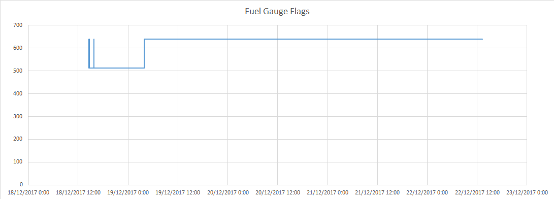
    Here's what I'm seeing in the log where we had an OCVTAKEN:

    So at the start you see some toggling of the flag which seems to indicate OCV measurements are performed (it changes from 640 to 512 decimal, so bit 7 is toggled = 128). But after that it stays low for a very long time (about 12 hours) which means the fuel gauge is now in relax mode. Only 12 hours later we get an OCVTAKEN and then the fuel gauge never goes back to relaxation mode.

    In any case, I will try to perform the test you described in the mean time.

    So for the test cycle we can basically use the scenario where we have the system plugged in for a long time, the fuel gauge should then perform an OCV measurement and then we rely on the fast qmax updates?

    Can you provide any information about the parameters for the fast qmax in flash configuration? You see, the default values seem to be set in such a way that a fast QMAX update is only performed at the very bottom of the SOC. However, in practice we are never discharging the battery that much (we only use about 60% of the total capacity as a safety measurement), so it would never reach that point. I guess I could change the threshold to a higher level, but I have no idea how that will impact the accuracy of the fast qmax algorithm.

    Kind regards,

    Sammy

  • Hi Sammy,

    For Qmax update, for the first learning cycle, a full 90% drop for the battery is required, but for subsequent cycles, only a 37% DOD drop is required as long as:

    The temperature range is between 10 and 40 degC
    The value is not taken in the disqualified voltage range of the battery
    The battery rests and a qualified OCV measurement is taken.

    You may not need to rely on Fast Qmax Update to update qmax. Please test first with fast qmax disabled. Once we have your system working properly, lets re-enable fast qmax, so the concerns are separated.

    Sincerely,
    Bryan Kahler
  • Hello Bryan,

    EDIT: sorry, I had missed your previous response regarding the additional requirements. What do you mean by first learning cycle? For the 90% discharge, does that mean that a fresh battery will always require some sort of learning cycle where we discharge the battery for 90%? I had understood this was part of the pre-production learning cycle and was stored in the flash (i.e. OCV table). I'll try to run a cycle where we discharge the battery to 5% SOC, wait for an OCV update, charge back up to 100% and wait for an additional OCV measurement. However, there are also some concerns about the SOC not being accurate enough, so the battery voltage might get below our system's deep discharge threshold votlage at such a low SOC. Can you also confirm we do not need to send the IT Enable command? I.e. IT is enabled automatically?

    My initial response (without reading your most recent post):

    We have seen the OCVTAKEN flag getting set, but only after a very long relax time and after it gets set it never gets toggled again (not sure if this is normal?). I have included an example log where the OCVTAKEN flag gets set (note this a few days after entering relax mode).

    log_ocv_toggled.xlsx

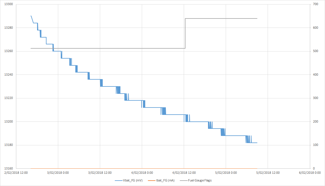
    In the following graph you can see the current is zero, so the fuel gauge should be in relax mode. OCVTAKEN flag is also low, which confirms this.

    It appears there is still some variation on the battery voltage (about 40mV in one day at the middle of the graph). The datasheet mentions:

    "After about 6 minutes in relaxation mode, the bq34z110 attempts to take accurate OCV readings. An additional requirement of dV/dt < 4 μV/s is required for the bq34z110 to perform Qmax updates."


    We're getting: 40mV/day, so in µV/s that would be: 40mV/(24 x 60 x 60) = 0.463µV/s. Maybe this is not entirely accurate. I don't know over what time the requirement is checked, but all this indicates that the fuel gauge should perform an OCV measurement.

    The dV/dt is higher at the start of the graph. About 24mV/6hours or 1.1µV/s, but that still well below the requirement of 4µV/s so I don't know why it's not performing the OCV measurement much sooner.

    We're currently running the test where we try to do QMAX updates after the OCVTAKEN flag is set.

    Some questions:

    • is the 4µV/s requirement fixed or can we change this somehow? I realise SOH will be less accurate if we take an OCV measurement while the battery voltage is still relaxing, but it would still be better than having no SOH at all.
    • Is it normal that the OCVTAKEN flag is set and then never gets reset during relaxation?

    Kind regards,

    Sammy

  • Hello Bryan,

    We did some more testing. First of all I want to mention we have now send the command ITENABLE and we're seeing some OCV measurements being made. In the previous tests we had not send this command so that might have been the issue...

    In any case, as before I have two tests running. Both are cycling between charge and discharge.

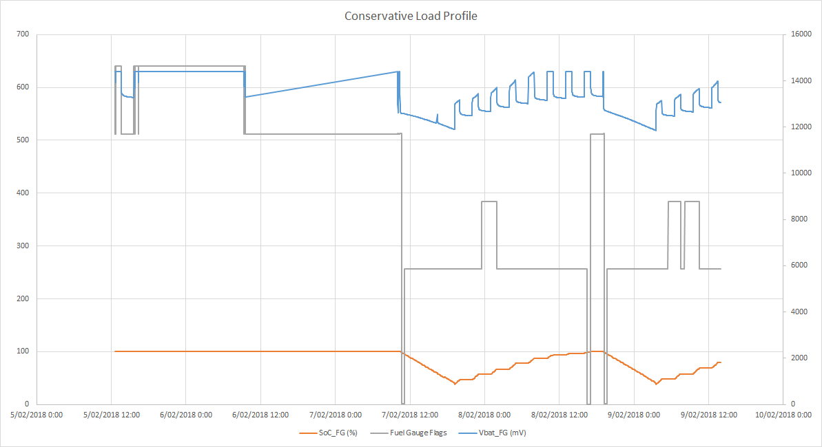
    • one with a conservative load and a (very) conservative SOC cutoff at 40% --> does not qualify as 90% DOD, just used to check if OCV measurements are being made
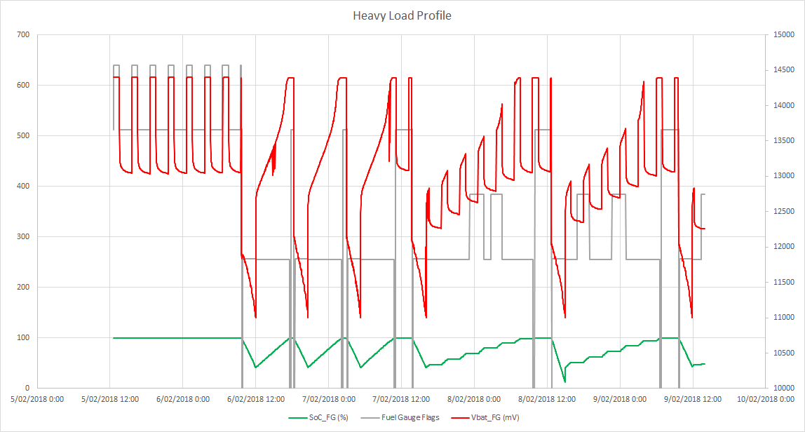
    • the other with a heavy load and cutoff at 5% --> this one should qualify as a 90% DOD

    In both cases I have added a periodic relax time during the charging cycle to allow the FG to perform OCV measurements. I am seeing sporadic toggles of the OCVTAKEN flag which seems to indicate it's working. However, I am unable to go down to a DOD of 90% as you suggest because the SOC value seems to be incorrect. In addition to the cutoff at 40%/5% we also have a cutoff if the battery reaches 10.8V to prevent deep discharge. The SOC at that point is still higher than 10% so we're not getting the full range. Maybe this is because the batteries are a bit older? We have cycled these pretty much non-stop for a couple of months so maybe that's why the SOC is wrong?

    I have included both log files as well.

    2402.logs.zip

    I expected the OCV measurements to "nudge" the SOC back to the correct position, but this does not seem to be the case. Note that we have also increased or charge voltages from 13.8V to 14.4V on request from the customer. Could this have an impact on the SOC measurement?

    Kind regards,

    Sammy

  • Hello Bryan,

    Could you have another look at our results please?

    Kind regards,

    Sammy

  • Hi Sammy,

    With respect to:

    EDIT: sorry, I had missed your previous response regarding the additional requirements. What do you mean by first learning cycle? For the 90% discharge, does that mean that a fresh battery will always require some sort of learning cycle where we discharge the battery for 90%? I had understood this was part of the pre-production learning cycle and was stored in the flash (i.e. OCV table). I'll try to run a cycle where we discharge the battery to 5% SOC, wait for an OCV update, charge back up to 100% and wait for an additional OCV measurement. However, there are also some concerns about the SOC not being accurate enough, so the battery voltage might get below our system's deep discharge threshold votlage at such a low SOC. Can you also confirm we do not need to send the IT Enable command? I.e. IT is enabled automatically?

    The IT Enable command will need to be sent. a 90% depth is discharge is required for the initial learning cycle. Once the gauge is learned with a status of 0x06, subsequent learning cycles will only require a DOD of 37%, assuming the OCV readings are not in the disqualified voltage range, or outside of other acceptable parameters for an update (such as temperature).

    0. Configure dataflash, pack chemistry, perform calibration and export GG File (for later comparison)
    1. Enable IT
    2. Send Reset command (0x0041)
    3. Charge the pack to charge termination.
    4. Rest until the OCVTAKEN flag sets
    5. C/7 Discharge to the termination voltage
    6. Rest until the OCVTAKEN flag sets. At this point, QMax should update and the Update Status should increment to 0x05
    7. Charge the pack to charge termination
    8. Rest until OCVTAKEN flag sets
    9. C/7 Discharge to the termination voltage
    10. Rest until the OCVTAKEN flag sets. At this point, the Ra table should update and Update Status should increment to 0x06

    Sincerely,
    Bryan Kahler