This thread has been locked.

If you have a related question, please click the "Ask a related question" button in the top right corner. The newly created question will be automatically linked to this question.

BQ40Z60: Charging current too high

Part Number: BQ40Z60
Other Parts Discussed in Thread: BQSTUDIO, BQ40Z50-R2

I have custom charger design, based on BQ40Z60 evaluation board, with changes:

- without all U1 protection circuit

- without precharge circuit: F1, Q7, C10, R18, R22

- AFEFUSE pin tied to GND

- R14 changed to 1K (we have high voltage drop on ACP pin after charge was enabled)

- C18, C20, C24, C25, C27 changed to 4,7uF/25V

- no Q10-Q13 led circuit

- voltage divider: R21 = 330k, sum of R26-R29 = 24k

- BQ40Z60 firmware: bq40z60_v0_15_build_21

- connected cells: 4x parallel NCR18650GA-Panasonic with thermistor and cables for balancer

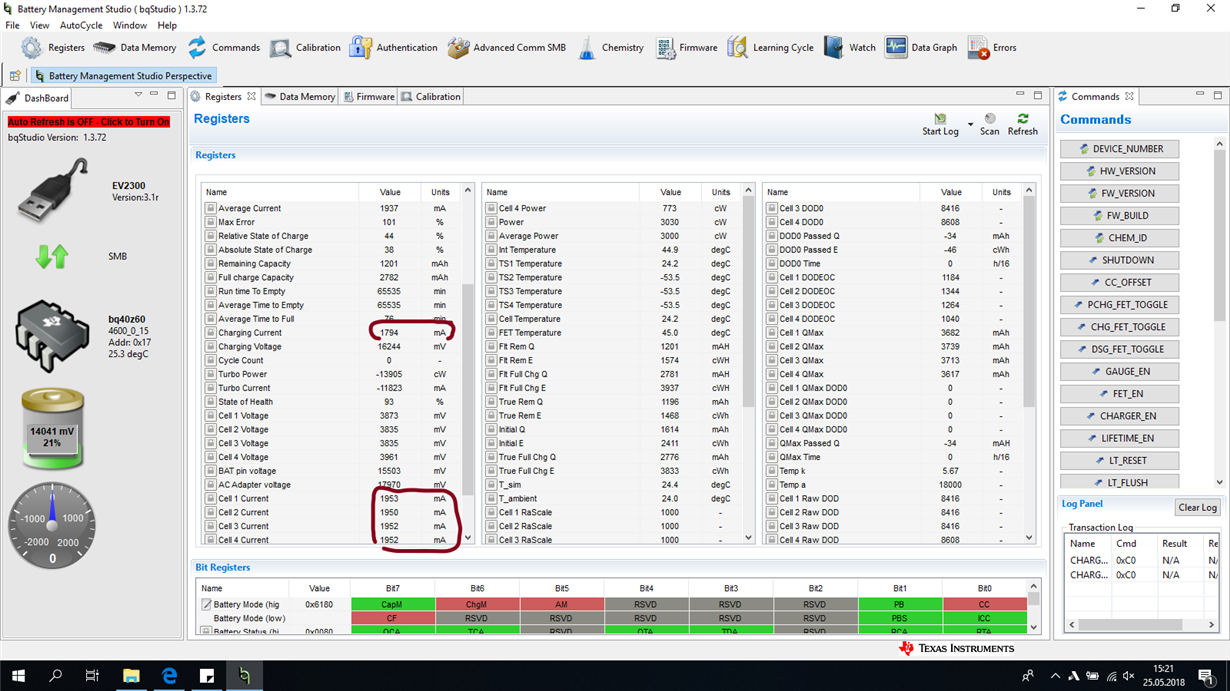
We have problem witch charging currents mismatch. BQ studio is reporting charging current to 1794mA, but for cell1-4 show about 1940mA. But to the cells is going about 2300mA (we connected 0.01R to +V4 cell, and measure voltage drop).

All voltages are calibrated and reported properly.

When I want to calibrate current (using that add-on 0.01Rfor metering), CC Gain, and Capacity Gain drops to 4.324. And all reported currents got messed up.

But sometimes I have "good" board, charging current 1794mA is almost the same as cell1-4 currents, but physically it delivers to battery about 2000mA. It works on the same golden image as other boards, only voltage calibration was done before metering.

How to fix that?

config-dump.gg.zip

  • Hi Mariusz,

    When there is no current present on the device, do you see the same offset? Or is this offset seen when loaded?

    Also, when performing the current calibration, are the following the steps as described in section 2.4 ( www.ti.com/.../slua734a.pdf )?

    Sincerely,
    Bryan Kahler
  • Without load or charging I have current 0 mA on each cell.

    I have done calibrations using only bqStudio 1.3.72

    After current calibration (using bqStudio) CC Offset and Capacity Gainn drops from 4.937 to 4.212. Now all reported currents match with measured charge/discharge current, but... desired charging current should be for example 1974mA (and shown by bqStudio), but cells real current is about 2300mA (also shown by bqStudio). Overcurrent protection is disabling charging. So it's possible to somehow calibrate current but it's not working properly.

    Is this documentation that you provided can resolve this mismatch readings? Is it better than calibration with bqStudio?

    Can somebody send me proper CSV file for bq40z60EVM board with properly calibrated currents for 4 cells Li-Ion pack? In my design, I'am using the same key parts as in EVM board (execpt R21 and R26-29).

  • Hi Mariusz,
    The ChargingCurrent( ) register is just the current which the gauge is recommending be used for the charging. This will depend on how you configured the various charging currents and voltages in dataflash.
    In a typical system with a separate gauge (like bq40z50-R2) and charger, the host would read ChargingCurrent() and ChargingVoltage() from the gauge and then tell the charger to use those settings (or as close to them as it can get based on the step-size it can achieve).
    The Cell X Current values are not directly measured, but estimated so will not match the AverageCurrent( ) register which is actually measured using the sense resistor.
  • Ok, but still something is wrong. Look at the screenshot on first post. AverageCurrent is 1937mA, ChargingCurrent is 1794mA, into battery goes about 2300mA. This is big mismatch. Sometimes I have "better" board (with closer to ideal currents). All current measuring resistors are the same values as in EVM board. 

    Current calibration with bqStudio gives me CCGain, Capacity Gain about 4.212 (very low value, but this 0.005R doesn't measure current in constant current mode charging).

  • Hi Mariusz,
    Does the gauge report current correctly in discharge mode, and at various current levels in both directions and across temperature?
  • Temperatures: +25C (standby), +55C (charging at 2,3A, input power supply 20V)
    Current:
    - no charge, no discharge = 0mA (good)
    - charging = big current mismatch (not good)
    - discharging = reported currents are ok (good)


    Charging at 0.8 to 1A show fairly good current. Charging at 1,5A gives higher error.
    So, higher charging current = higher error at reported current.
    To measure current, Im using 0.01R drop resistor at +VBAT (top stack cell). Can it be measuring error? I tried 2 different multimeters, but dropout voltage measurements are the same.

  • Hi Mariusz,
    That might be a good clue that the current reported is accurate in the discharge direction (all currents) and in the charge direction (at <1A), but the error is only at higher charge currents. I presume things are getting quite hot at high charge current (but not as much at high discharge current) and the high temperature might be affecting the resistance of your resistor that you inserted at +VBAT. What is the temperature coefficient (PPM) of that 0.01R you are using? Are you physically measuring on the resistor terminals directly (Kelvin connection) or via some test points?
    Can you check the resistance across temperature from wherever you are measuring?
  • Hello Mariusz,

    You are likely dealing with a noise related problem due to sensitive nature of using this dual function (gauge, NVDC charger) bq40z60 device. There has been advice to not use the bq40z60 in this forum due to the difficult layout necessary when using this device… but when following the layout recommendations (refer to latest datasheet and EVM layout) or utilizing a common mode filter on the kelvin networks (CC RSNS, Charger RSNS) you can get reasonably good performance from the bq40z60.

    I have been involved in three HW designs using the bq40z60 and each has undergone more than one board layout and BOM changes to get the kelvin measurements clean. In the situation you describe, you are likely dealing with noise on the CC RSNS (5 mOhm) kelvin when the charger is active. The noise generated from the NVDC buck is transmitted through your board and entering the SRN/SRP pins causing an offset in the BQ current measurement. You will need to analyze several boards that you build as each will produce a unique noise signature where the layout and filter components influence the nose floor. It sounds like you are experiencing this where some boards produce acceptable current measurements, yet other are poor performers.

    Note that the use of a 5 mOhm RSNS should produce calibration for CC Gain and Capacity gain of 5.000 (+/- the tolerance of the resistor). Your calibration is ranging from 4.212 to 4.937 – this is a definite clue that you are dealing with kelvin measurement problems across the population of boards.

     BR,

    BB

  • Hi Brad

    That was very helpful answer. We will go that way (make new board project).