This thread has been locked.

If you have a related question, please click the "Ask a related question" button in the top right corner. The newly created question will be automatically linked to this question.

BQ40Z50-R1: the batteries connected to the bms are empty in a few weeks

Part Number: BQ40Z50-R1
Other Parts Discussed in Thread: BQ40Z50

Dear TI Battery Management Team,


I'm seeing a very similar issue on a 4-cell design using the bq40z50-R1.  With all four cells connected, in Normal mode I'm seeing a draw on -2.8mA.

I'm not using the LED's so they are left floating and the DISP pin is pulled low.

Also of note, when disconnecting the cells in the series stack, the current draw drops.

In the related thread, a component was found to be the culprit, although I don't know what that component would be in our design as we kept it very bare bones.

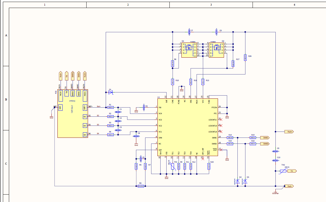
A schematic is provided below.  I can also provide other documents in needed.

Thank you,

Kevin

  • Kevin,

    I can't read the values of the components in the schematic captured here. Please post your sch as a pdf'd attachment. Once I have it, I'll check out the schematic in the next couple of days. Can you also point me to the other thread please that you mention here?
  • 4-cell_bq40z50-r1_bms.pdfHi Batt,

    Attached is a pdf of the schematic.

    Here is a link to the thread in regards to same issue:

    Thank you,

    Kevin

  • remove the 10k on your PRES pin. You are competing with PBI and that's going to give you a leakage path. Go straight to GND and you should have it work.
  • Unfortunately that didn't resolve the issue. With a meter in line on the most negative cell connection, I'm seeing a draw of -2350uA. When going from normal mode to sleep mode the current draw drops to about -2000uA which is to be expected.
    Somehow the board is drawing an extra 2mA all the time.

    We are also have a 2-cell version of this design and I'm seeing exactly half the current draw from that board (about -1150uA in normal mode and -800uA in sleep mode).

    So the extra current draw is proportional to amount of cells connected. We are using NCR18650B cells and have the proper Chem ID set.
    The pack has also gone through a successful learning cycle.

    This is the second design we've based around the bq40z50 with similar current draw issues. On the first one, we weren't using LED's and pulled those low as recommended in the datasheet. Thinking that was the cause of the excessive current draw within that design, we left those pins remain floating on this new board, which has since been recommended.

    Any other ideas as to what else may be causing this issue?
    Thank you.

    Best Regards,
    Kevin
  • OK, Kevin. I'll take a deeper look into this. That seemed like the obvious issue, but there may be other elements. However, please do keep that suggestion. Do not populate the 10k and go straight to GND. I'll see if I can debug this within the next few days.
  • Thank you, Batt. I appreciate the help.
    Best Regards,
    Kevin
  • Hello,

    Here is something I observed while connecting the cells:
    With a current meter in-line on Bat - , I can see the current draw increase as I connect each cell in series. The draw with B4 connected is -0.16mA, B3 connected next increases the draw to -0.80mA, B2 connected draws -1.50mA and finally Bat + connected gives the overall -2.3mA draw I've been seeing.

    As noted, the design we have using Two cells in series is drawing about half the amount of excess current.

    Other than the what appears to be an extra 2.0mA draw, the pack is functioning perfectly. Gauging is accurate and all protection features are working as they should.

    Thank you,
    Kevin
  • I'm wondering if having the PCHG pin pulled to ground is causing the issue?  

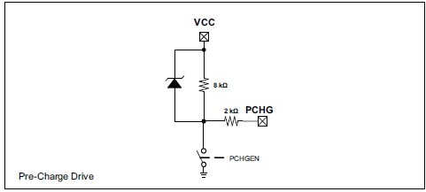
    We aren't using the pre-charge feature, but in the datasheet it shows that pin tied to Vcc with an 8kohm and a 2kohm resistor in-line.

    So even though it isn't being used, that resistance can still be pulled low.

    It will be difficult for me to prove it with the prototype board I have because the pins on the bq40z50 are so small, and the trace to ground isn't in a place where I can cut it.  I will try however to see if I can pull it off.

    Any thoughts as to if this is the cause of the extra current draw?

    Best Regards,

    Kevin

  • Hi Kevin,

    Yes, that could be it. It's internally muxed and the afe scans it when the PCHG fet is enabled. I suppose you are using PCHG_COMM bit in settings and using the CHG fet as the charge fet during precharge conditions. Sorry, I should have seen this in the schematic earlier. If you aren't using the PCHG fet drive, let it float.

    The proportionality of the current to the number of cells suggests a leakage path across the cells, the only way this can be true is if it's via VCC which is connected to PCHG internally.
  • Hi Batt,

    Thanks for the quick reply. Yes, we have the PCHG_COMM bit set and are using the CHG Fet for precharge conditions. I will attempt to remove that pin or cut the trace to the ground path to have it float. That was the only thing I saw that would have a path from Vcc to Ground so I'm thinking that had to have been the problem.

    Thanks much,

    Kevin