This thread has been locked.

If you have a related question, please click the "Ask a related question" button in the top right corner. The newly created question will be automatically linked to this question.

BQ20Z45-R1: CFETF Failure Even Though the Charge FET is Off

Part Number: BQ20Z45-R1
Other Parts Discussed in Thread: EV2400

We under-charge some batteries in our product line.  Some chargers do not communicate with our batteries and are over-charged due to the settings in the gg file.  We were under the impression that when a full charge happens, the charge FET gets pulled (at some point) and no current can flow.  It seems that the charge FET gets pulled and we get a CFETF permanent failure, even with a 20 second failure time.  

How is current still flowing where we get this error?

Is there any way to prevent this failure?


  • Hi David,

    I'm not so familiar myself with this device, will have to look into it more. Can you send a gg file with your settings, and a log showing the events you are describing? It seems your log should show a current > 20mA after the CHG FET is disabled for the CFETF to occur, do you know if this is happening (and why it would happen)? Are you using a ZVCHG precharge FET?

    Normal charging generally doesn't result in the CHG FET being disabled at full charge, that would normally occur when you have reached an overvoltage condition. You may have the CHG FET disabled if the pack is removable and is removed from the system ([PRES]=1).

    Thanks,

    Terry
  • We do not have a log because the errors happen in the field.  The chargers that communicate with the battery, charge normally at 16.1V.  Some of the legacy chargers attempt to charge the battery to 16.8V.  In the lab, the battery's charge FET would turn off and the battery would be fine.  

    Failed - Copy.txt
    [Header]
    bq EVSW Version = 0.9.64	
    DeviceName = bq20z45R1 v1.05
    Time = 08/13/18 2:22:33 PM	
    
    
    [Voltage(1st Level Safety)]
    LT COV Threshold = 4100
    LT COV Recovery = 4050
    ST COV Threshold = 4100
    ST COV Recovery = 4050
    HT COV Threshold = 4100
    HT COV Recovery = 4050
    CUV Threshold = 2500
    CUV Time = 2
    CUV Recovery = 2800
    [Current(1st Level Safety)]
    OC (1st Tier) Chg = 7000
    OC (1st Tier) Dsg = 20000
    OC (1st Tier) Dsg Time = 2
    Current Recovery Time = 8
    AFE OC Dsg = 1B
    AFE OC Dsg Time = 0F
    AFE SC Chg Cfg = 74
    AFE SC Dsg Cfg = FF
    [Temperature(1st Level Safety)]
    OT1 Chg Threshold = 60.0
    OT1 Chg Time = 2
    OT1 Chg Recovery = 55.0
    OT2 Chg Threshold = 60.0
    OT2 Chg Time = 0
    OT2 Chg Recovery = 55.0
    OT1 Dsg Threshold = 65.0
    OT1 Dsg Time = 2
    OT1 Dsg Recovery = 60.0
    OT2 Dsg Threshold = 65.0
    OT2 Dsg Time = 0
    OT2 Dsg Recovery = 60.0
    Hi Dsg Start Temp = 60.0
    
    [Voltage(2nd Level Safety)]
    LT SOV Threshold = 4200
    ST SOV Threshold = 4200
    HT SOV Threshold = 4200
    SOV Time = 5
    PF SOV Fuse Blow Delay = 10
    SUV Threshold = 2000
    SUV Time = 0
    Rest CIM Current = 5
    Rest CIM Fail Voltage = 1000
    Rest CIM Time = 0
    CIM Battery Rest Time = 1800
    Rest CIM Check Voltage = 3000
    Active CIM Fail Voltage = 1000
    Active CIM Time = 0
    Active CIM Check Voltage = 3000
    PFIN Detect Time = 0
    PF Min Fuse Blow Voltage = 8000
    [Current(2nd Level Safety)]
    SOC Chg = 20000
    SOC Chg Time = 1
    SOC Dsg = 30000
    SOC Dsg Time = 10
    [Temperature(2nd Level Safety)]
    SOT1 Chg Threshold = 65.0
    SOT1 Chg Time = 5
    SOT2 Chg Threshold = 65.0
    SOT2 Chg Time = 0
    SOT1 Dsg Threshold = 75.0
    SOT1 Dsg Time = 5
    SOT2 Dsg Threshold = 75.0
    SOT2 Dsg Time = 0
    [FET Verification(2nd Level Safety)]
    FET Fail Time = 20
    [AFE Verification(2nd Level Safety)]
    AFE Check Time = 120
    AFE Fail Limit = 20
    AFE Fail Recovery Time = 20
    
    [Charge Temp Cfg(Charge Control)]
    JT1 = 0.0
    JT2 = 12.0
    JT2a = 30.0
    JT3 = 45.0
    JT4 = 60.0
    Temp Hys = 1.0
    [Pre-Charge Cfg(Charge Control)]
    Pre-chg Voltage Threshold = 2500
    Pre-chg Recovery Voltage = 2700
    Pre-chg Current = 250
    [Charge Cfg(Charge Control)]
    LT Chg Voltage = 16100
    LT Chg Current1 = 600
    LT Chg Current2 = 600
    LT Chg Current3 = 600
    ST1 Chg Voltage = 16100
    ST1 Chg Current1 = 6000
    ST1 Chg Current2 = 6000
    ST1 Chg Current3 = 6000
    ST2 Chg Voltage = 16100
    ST2 Chg Current1 = 6000
    ST2 Chg Current2 = 6000
    ST2 Chg Current3 = 6000
    HT Chg Voltage = 16100
    HT Chg Current1 = 6000
    HT Chg Current2 = 6000
    HT Chg Current3 = 6000
    Cell Voltage Threshold1 = 3900
    Cell Voltage Threshold2 = 4000
    Cell Voltage Thresh Hys = 10
    [Termination Cfg.(Charge Control)]
    Taper Current = 250
    Taper Voltage = 75
    TCA Clear % = 99
    FC Clear % = 99
    [Cell Balancing Cfg(Charge Control)]
    Min Cell Deviation = 1350
    [Charging Faults(Charge Control)]
    Over Charge Capacity = 500
    Charge Fault Cfg = 00
    
    [Data(SBS Configuration)]
    Rem Cap Alarm = 1000
    Rem Energy Alarm = 14400
    Rem Time Alarm = 10
    Init Battery Mode = 0081
    Design Voltage = 14100
    Spec Info = 0031
    Manuf Date = 
    Ser. Num. = 0162
    Cycle Count = 0
    CC Threshold = 6750
    CF MaxError Limit = 100
    Design Capacity = 6900
    Design Energy = 97290
    Manuf Name = 
    Device Name = 
    Device Chemistry = LION
    Deterioration Warn Limit = 50
    Deterioration Fault Limit = 30
    Cell Life Limit = 20
    [Configuration(SBS Configuration)]
    TDA Set % = 6
    TDA Clear % = 8
    FD Set % = 2
    FD Clear % = 5
    TDA Set Volt Threshold = 11000
    TDA Set Volt Time = 5
    TDA Clear Volt = 11100
    
    [Manufacturer Info(System Data)]
    Manuf. Info 0 = 
    Manuf. Block 1 = 20151119 00240
    Manuf. Block 2 = 
    Manuf. Block 3 = Rev 6
    Manuf. Block 4 = 0123456789ABCDEF0123
    [Lifetime Data(System Data)]
    Lifetime Max Temp = 33.5
    Lifetime Min Temp = 21.4
    Lifetime Max Cell Voltage = 4124
    Lifetime Min Cell Voltage = 2500
    Lifetime Max Pack Voltage = 16462
    Lifetime Min Pack Voltage = 13998
    Lifetime Max Chg Current = 4145
    Lifetime Max Dsg Current = -1000
    Lifetime Max Chg Power = 64660
    Lifetime Max Dsg Power = -14860
    Life Max AvgDsg Cur = -1991
    Life Max AvgDsg Pow = -2819
    Life Avg Temp = 24.1
    [Lifetime Temp Samples(System Data)]
    LT Temp Samples = 1827
    
    [Registers(Configuration)]
    Operation Cfg A = 0329
    Operation Cfg B = 2CC8
    Operation Cfg C = 0100
    Permanent Fail Cfg = 0FFF
    Permanent Fail Cfg 2 = 0007
    Non-Removable Cfg = 3007
    [AFE(Configuration)]
    AFE.State_CTL = 00
    
    [Power(Power)]
    Flash Update OK Voltage = 7500
    Shutdown Voltage = 9500
    Shutdown Time = 10
    Cell Shutdown Voltage = 2200
    Cell Shutdown Time = 10
    Charger Present = 16150
    Sleep Current = 10
    Wake Current Reg = 02
    Sealed Ship Delay = 5
    
    [IT Cfg(Gas Gauging)]
    Load Select = 7
    Load Mode = 0
    Term Voltage = 10000
    User Rate-mA = 0
    User Rate-mW = 0
    Reserve Cap-mAh = 0
    Reserve Cap-mWh = 0
    Ra Max Delta = 44
    [Current Thresholds(Gas Gauging)]
    Dsg Current Threshold = 100
    Chg Current Threshold = 50
    Quit Current = 10
    [State(Gas Gauging)]
    Qmax Cell 0 = 8842
    Qmax Cell 1 = 8835
    Qmax Cell 2 = 8842
    Qmax Cell 3 = 8861
    Qmax Pack = 8835
    Update Status = 0E
    Cell 0 Chg dod at EoC = 2232
    Cell 1 Chg dod at EoC = 2232
    Cell 2 Chg dod at EoC = 2232
    Cell 3 Chg dod at EoC = 2232
    Avg I Last Run = -1991
    Avg P Last Run = -2819
    Delta Voltage = 17
    Max Avg I Last Run = -1992
    Max Avg P Last Run = -3141
    
    [R_a0(Ra Table)]
    Cell0 R_a flag = 0055
    Cell0 R_a 0 = 93
    Cell0 R_a 1 = 95
    Cell0 R_a 2 = 112
    Cell0 R_a 3 = 89
    Cell0 R_a 4 = 52
    Cell0 R_a 5 = 31
    Cell0 R_a 6 = 29
    Cell0 R_a 7 = 22
    Cell0 R_a 8 = 24
    Cell0 R_a 9 = 28
    Cell0 R_a 10 = 41
    Cell0 R_a 11 = 64
    Cell0 R_a 12 = 123
    Cell0 R_a 13 = 220
    Cell0 R_a 14 = 4433
    [R_a1(Ra Table)]
    Cell1 R_a flag = 0055
    Cell1 R_a 0 = 93
    Cell1 R_a 1 = 94
    Cell1 R_a 2 = 111
    Cell1 R_a 3 = 88
    Cell1 R_a 4 = 51
    Cell1 R_a 5 = 30
    Cell1 R_a 6 = 27
    Cell1 R_a 7 = 21
    Cell1 R_a 8 = 22
    Cell1 R_a 9 = 26
    Cell1 R_a 10 = 39
    Cell1 R_a 11 = 61
    Cell1 R_a 12 = 121
    Cell1 R_a 13 = 222
    Cell1 R_a 14 = 4496
    [R_a2(Ra Table)]
    Cell2 R_a flag = 0000
    Cell2 R_a 0 = 91
    Cell2 R_a 1 = 92
    Cell2 R_a 2 = 109
    Cell2 R_a 3 = 84
    Cell2 R_a 4 = 47
    Cell2 R_a 5 = 27
    Cell2 R_a 6 = 24
    Cell2 R_a 7 = 18
    Cell2 R_a 8 = 20
    Cell2 R_a 9 = 26
    Cell2 R_a 10 = 36
    Cell2 R_a 11 = 59
    Cell2 R_a 12 = 113
    Cell2 R_a 13 = 208
    Cell2 R_a 14 = 4164
    [R_a3(Ra Table)]
    Cell3 R_a flag = 0055
    Cell3 R_a 0 = 93
    Cell3 R_a 1 = 95
    Cell3 R_a 2 = 112
    Cell3 R_a 3 = 89
    Cell3 R_a 4 = 52
    Cell3 R_a 5 = 31
    Cell3 R_a 6 = 29
    Cell3 R_a 7 = 22
    Cell3 R_a 8 = 24
    Cell3 R_a 9 = 28
    Cell3 R_a 10 = 41
    Cell3 R_a 11 = 65
    Cell3 R_a 12 = 127
    Cell3 R_a 13 = 231
    Cell3 R_a 14 = 4633
    [R_a0x(Ra Table)]
    xCell0 R_a flag = 0000
    xCell0 R_a 0 = 93
    xCell0 R_a 1 = 95
    xCell0 R_a 2 = 112
    xCell0 R_a 3 = 89
    xCell0 R_a 4 = 52
    xCell0 R_a 5 = 31
    xCell0 R_a 6 = 29
    xCell0 R_a 7 = 22
    xCell0 R_a 8 = 24
    xCell0 R_a 9 = 28
    xCell0 R_a 10 = 41
    xCell0 R_a 11 = 64
    xCell0 R_a 12 = 123
    xCell0 R_a 13 = 221
    xCell0 R_a 14 = 4453
    [R_a1x(Ra Table)]
    xCell1 R_a flag = 0000
    xCell1 R_a 0 = 93
    xCell1 R_a 1 = 94
    xCell1 R_a 2 = 111
    xCell1 R_a 3 = 88
    xCell1 R_a 4 = 51
    xCell1 R_a 5 = 30
    xCell1 R_a 6 = 27
    xCell1 R_a 7 = 21
    xCell1 R_a 8 = 22
    xCell1 R_a 9 = 26
    xCell1 R_a 10 = 39
    xCell1 R_a 11 = 61
    xCell1 R_a 12 = 121
    xCell1 R_a 13 = 218
    xCell1 R_a 14 = 4415
    [R_a2x(Ra Table)]
    xCell2 R_a flag = 0055
    xCell2 R_a 0 = 91
    xCell2 R_a 1 = 92
    xCell2 R_a 2 = 109
    xCell2 R_a 3 = 84
    xCell2 R_a 4 = 47
    xCell2 R_a 5 = 27
    xCell2 R_a 6 = 24
    xCell2 R_a 7 = 18
    xCell2 R_a 8 = 20
    xCell2 R_a 9 = 26
    xCell2 R_a 10 = 36
    xCell2 R_a 11 = 59
    xCell2 R_a 12 = 113
    xCell2 R_a 13 = 216
    xCell2 R_a 14 = 4324
    [R_a3x(Ra Table)]
    xCell3 R_a flag = 0000
    xCell3 R_a 0 = 93
    xCell3 R_a 1 = 95
    xCell3 R_a 2 = 112
    xCell3 R_a 3 = 89
    xCell3 R_a 4 = 52
    xCell3 R_a 5 = 31
    xCell3 R_a 6 = 29
    xCell3 R_a 7 = 22
    xCell3 R_a 8 = 24
    xCell3 R_a 9 = 28
    xCell3 R_a 10 = 41
    xCell3 R_a 11 = 65
    xCell3 R_a 12 = 127
    xCell3 R_a 13 = 229
    xCell3 R_a 14 = 4593
    
    [Device Status Data(PF Status)]
    Saved PF Flags 1 = 0020
    Saved PF Flags 2 = 0000
    Saved 1st PF Flags 1 = 0020
    Saved 1st PF Flags 2 = 0000
    
    [Data(Calibration)]
    CC Gain = 5.082
    CC Delta = 5.082
    Ref Voltage = 1224.75
    AFE Pack Gain = 672.91
    CC Offset = -0.264
    Board Offset = -27.5
    Int Temp Offset = 5.9
    Ext1 Temp Offset = -1.8
    Ext2 Temp Offset = 0.0
    [Config(Calibration)]
    CC Current = 3000
    Voltage Signal = 12600
    Temp Signal = 298.0
    CC Offset Time = 250
    ADC Offset Time = 32
    CC Gain Time = 250
    Voltage Time = 1888
    Temperature Time = 32
    Cal Mode Timeout = 300
    [Temp Model(Calibration)]
    Ext Coef 1 = -28285
    Ext Coef 2 = 20848
    Ext Coef 3 = -7537
    Ext Coef 4 = 401.2
    Ext Min AD = 0
    Ext Max Temp = 401.2
    Int Coef 1 = 0
    Int Coef 2 = 0
    Int Coef 3 = -11136
    Int Coef 4 = 575.4
    Int Min AD = 0
    Int Max Temp = 575.4
    [Current(Calibration)]
    Filter = 239
    Deadband = 75
    CC Deadband = 10.0
    

  • Thanks for the logs, please expect to hear from us in 2 days.
  • Hi David,

    Have you tried recreating a similar case with this pack, clearing the PF, applying the higher voltage charging voltage, and seeing if you can somehow recreate the failure? Given you have been in production awhile, some possibilities would be (a) malfunction/failure of the bq20z45, (b) malfunction/failure of your FETs, (c) board-level issue/fail. So it would be good if you can be working to narrow down to which is the issue, are you confident it isn't something related to the FETs or board?

    When you are seeing these fails, how long have the boards been in operation at that point? Are they failing early in their life or after some moderate usage by the end customer?

    Can you send the schematic?

    Thanks,

    Terry
  • I am currently trying to re-create the issue on my bench doing exactly what you said. So far, there has not been a permanent failure. I am currently using a battery that has failed in the field. The FETs are working properly so far. I am not confident that there is not an issue with the board which is why I am trying all options. I do not fully understand the problem. It seems like if the FET was off, then there should not be any charge current. Can you private message me your email address so I can send you the schematic?
  • I looked through the schematic, nothing spiked out as an issue from initial review. Another possibility would be if the current measurement was corrupted somehow, so even with zero current, the device believes it is seeing current flowing. When you retest the previously failed board, is the current msmt still look accurate, with little/no offset?
  • Yes. That is actually one of the first things I look for, in hope to find an error in production when calibrating, etc the batteries.
  • One additional item that was a little odd in your gg file:

    Lifetime Max Dsg Current = -1000
    Life Max AvgDsg Cur = -1991

    It seemed unlikely to have a raw current that only hit 1000mA, while the averaged value hit 1991mA. It turns out the averaged version is only updated at grid points, but that also doesn't explain this. I wonder if maybe you have a value in your golden file that was loaded initially, and it just never got updated? Can you provide your golden gg file that you use to initialize devices during production?

    Thanks,

    Terry
  • Here is the golden GG (I had to rename it to a txt file.  This forum will not take the .gg or .senc)

    Golden.txt
    [Header]
    bq EVSW Version = 0.9.64	
    DeviceName = bq20z45R1 v1.05
    Time = 01/10/18 8:49:09 AM	
    
    
    [Voltage(1st Level Safety)]
    LT COV Threshold = 4100
    LT COV Recovery = 4050
    ST COV Threshold = 4100
    ST COV Recovery = 4050
    HT COV Threshold = 4100
    HT COV Recovery = 4050
    CUV Threshold = 2500
    CUV Time = 2
    CUV Recovery = 2800
    [Current(1st Level Safety)]
    OC (1st Tier) Chg = 7000
    OC (1st Tier) Dsg = 20000
    OC (1st Tier) Dsg Time = 2
    Current Recovery Time = 8
    AFE OC Dsg = 1B
    AFE OC Dsg Time = 0F
    AFE SC Chg Cfg = 74
    AFE SC Dsg Cfg = FF
    [Temperature(1st Level Safety)]
    OT1 Chg Threshold = 60.0
    OT1 Chg Time = 2
    OT1 Chg Recovery = 55.0
    OT2 Chg Threshold = 60.0
    OT2 Chg Time = 0
    OT2 Chg Recovery = 55.0
    OT1 Dsg Threshold = 65.0
    OT1 Dsg Time = 2
    OT1 Dsg Recovery = 60.0
    OT2 Dsg Threshold = 65.0
    OT2 Dsg Time = 0
    OT2 Dsg Recovery = 60.0
    Hi Dsg Start Temp = 60.0
    
    [Voltage(2nd Level Safety)]
    LT SOV Threshold = 4200
    ST SOV Threshold = 4200
    HT SOV Threshold = 4200
    SOV Time = 5
    PF SOV Fuse Blow Delay = 10
    SUV Threshold = 2000
    SUV Time = 0
    Rest CIM Current = 5
    Rest CIM Fail Voltage = 1000
    Rest CIM Time = 0
    CIM Battery Rest Time = 1800
    Rest CIM Check Voltage = 3000
    Active CIM Fail Voltage = 1000
    Active CIM Time = 0
    Active CIM Check Voltage = 3000
    PFIN Detect Time = 0
    PF Min Fuse Blow Voltage = 8000
    [Current(2nd Level Safety)]
    SOC Chg = 20000
    SOC Chg Time = 1
    SOC Dsg = 30000
    SOC Dsg Time = 10
    [Temperature(2nd Level Safety)]
    SOT1 Chg Threshold = 65.0
    SOT1 Chg Time = 5
    SOT2 Chg Threshold = 65.0
    SOT2 Chg Time = 0
    SOT1 Dsg Threshold = 75.0
    SOT1 Dsg Time = 5
    SOT2 Dsg Threshold = 75.0
    SOT2 Dsg Time = 0
    [FET Verification(2nd Level Safety)]
    FET Fail Time = 20
    [AFE Verification(2nd Level Safety)]
    AFE Check Time = 120
    AFE Fail Limit = 20
    AFE Fail Recovery Time = 20
    
    [Charge Temp Cfg(Charge Control)]
    JT1 = 0.0
    JT2 = 12.0
    JT2a = 30.0
    JT3 = 45.0
    JT4 = 60.0
    Temp Hys = 1.0
    [Pre-Charge Cfg(Charge Control)]
    Pre-chg Voltage Threshold = 2500
    Pre-chg Recovery Voltage = 2700
    Pre-chg Current = 250
    [Charge Cfg(Charge Control)]
    LT Chg Voltage = 16100
    LT Chg Current1 = 600
    LT Chg Current2 = 600
    LT Chg Current3 = 600
    ST1 Chg Voltage = 16100
    ST1 Chg Current1 = 6000
    ST1 Chg Current2 = 6000
    ST1 Chg Current3 = 6000
    ST2 Chg Voltage = 16100
    ST2 Chg Current1 = 6000
    ST2 Chg Current2 = 6000
    ST2 Chg Current3 = 6000
    HT Chg Voltage = 16100
    HT Chg Current1 = 6000
    HT Chg Current2 = 6000
    HT Chg Current3 = 6000
    Cell Voltage Threshold1 = 3900
    Cell Voltage Threshold2 = 4000
    Cell Voltage Thresh Hys = 10
    [Termination Cfg.(Charge Control)]
    Taper Current = 250
    Taper Voltage = 75
    TCA Clear % = 99
    FC Clear % = 99
    [Cell Balancing Cfg(Charge Control)]
    Min Cell Deviation = 1350
    [Charging Faults(Charge Control)]
    Over Charge Capacity = 500
    Charge Fault Cfg = 00
    
    [Data(SBS Configuration)]
    Rem Cap Alarm = 1000
    Rem Energy Alarm = 14400
    Rem Time Alarm = 10
    Init Battery Mode = 0081
    Design Voltage = 14100
    Spec Info = 0031
    Manuf Date = 03-Dec-2015
    Ser. Num. = 0162
    Cycle Count = 0
    CC Threshold = 6750
    CF MaxError Limit = 100
    Design Capacity = 6900
    Design Energy = 97290
    Manuf Name = 
    Device Name = 
    Device Chemistry = LION
    Deterioration Warn Limit = 50
    Deterioration Fault Limit = 30
    Cell Life Limit = 20
    [Configuration(SBS Configuration)]
    TDA Set % = 6
    TDA Clear % = 8
    FD Set % = 2
    FD Clear % = 5
    TDA Set Volt Threshold = 11000
    TDA Set Volt Time = 5
    TDA Clear Volt = 11100
    
    [Manufacturer Info(System Data)]
    Manuf. Info 0 = 
    Manuf. Block 1 = 20151119 00240
    Manuf. Block 2 = 
    Manuf. Block 3 = Rev 6
    Manuf. Block 4 = 0123456789ABCDEF0123
    [Lifetime Data(System Data)]
    Lifetime Max Temp = 22.0
    Lifetime Min Temp = 22.0
    Lifetime Max Cell Voltage = 2500
    Lifetime Min Cell Voltage = 2500
    Lifetime Max Pack Voltage = 14100
    Lifetime Min Pack Voltage = 14100
    Lifetime Max Chg Current = 1000
    Lifetime Max Dsg Current = -1000
    Lifetime Max Chg Power = 0
    Lifetime Max Dsg Power = 0
    Life Max AvgDsg Cur = 0
    Life Max AvgDsg Pow = 0
    Life Avg Temp = 22.0
    [Lifetime Temp Samples(System Data)]
    LT Temp Samples = 0
    
    [Registers(Configuration)]
    Operation Cfg A = 0329
    Operation Cfg B = 2CC8
    Operation Cfg C = 0100
    Permanent Fail Cfg = 0FFF
    Permanent Fail Cfg 2 = 0007
    Non-Removable Cfg = 3007
    [AFE(Configuration)]
    AFE.State_CTL = 00
    
    [Power(Power)]
    Flash Update OK Voltage = 7500
    Shutdown Voltage = 9500
    Shutdown Time = 10
    Cell Shutdown Voltage = 2200
    Cell Shutdown Time = 10
    Charger Present = 16150
    Sleep Current = 10
    Wake Current Reg = 02
    Sealed Ship Delay = 5
    
    [IT Cfg(Gas Gauging)]
    Load Select = 7
    Load Mode = 0
    Term Voltage = 10000
    User Rate-mA = 0
    User Rate-mW = 0
    Reserve Cap-mAh = 0
    Reserve Cap-mWh = 0
    Ra Max Delta = 44
    [Current Thresholds(Gas Gauging)]
    Dsg Current Threshold = 100
    Chg Current Threshold = 50
    Quit Current = 10
    [State(Gas Gauging)]
    Qmax Cell 0 = 8557
    Qmax Cell 1 = 8555
    Qmax Cell 2 = 8562
    Qmax Cell 3 = 8562
    Qmax Pack = 8555
    Update Status = 06
    Cell 0 Chg dod at EoC = 2232
    Cell 1 Chg dod at EoC = 2232
    Cell 2 Chg dod at EoC = 2232
    Cell 3 Chg dod at EoC = 2232
    Avg I Last Run = -1991
    Avg P Last Run = -2819
    Delta Voltage = 17
    Max Avg I Last Run = -1992
    Max Avg P Last Run = -3141
    
    [R_a0(Ra Table)]
    Cell0 R_a flag = 0055
    Cell0 R_a 0 = 93
    Cell0 R_a 1 = 95
    Cell0 R_a 2 = 112
    Cell0 R_a 3 = 89
    Cell0 R_a 4 = 52
    Cell0 R_a 5 = 31
    Cell0 R_a 6 = 29
    Cell0 R_a 7 = 22
    Cell0 R_a 8 = 24
    Cell0 R_a 9 = 28
    Cell0 R_a 10 = 41
    Cell0 R_a 11 = 64
    Cell0 R_a 12 = 123
    Cell0 R_a 13 = 220
    Cell0 R_a 14 = 4433
    [R_a1(Ra Table)]
    Cell1 R_a flag = 0055
    Cell1 R_a 0 = 93
    Cell1 R_a 1 = 94
    Cell1 R_a 2 = 111
    Cell1 R_a 3 = 88
    Cell1 R_a 4 = 51
    Cell1 R_a 5 = 30
    Cell1 R_a 6 = 27
    Cell1 R_a 7 = 21
    Cell1 R_a 8 = 22
    Cell1 R_a 9 = 26
    Cell1 R_a 10 = 39
    Cell1 R_a 11 = 61
    Cell1 R_a 12 = 121
    Cell1 R_a 13 = 222
    Cell1 R_a 14 = 4496
    [R_a2(Ra Table)]
    Cell2 R_a flag = 0000
    Cell2 R_a 0 = 91
    Cell2 R_a 1 = 92
    Cell2 R_a 2 = 109
    Cell2 R_a 3 = 84
    Cell2 R_a 4 = 47
    Cell2 R_a 5 = 27
    Cell2 R_a 6 = 24
    Cell2 R_a 7 = 18
    Cell2 R_a 8 = 20
    Cell2 R_a 9 = 26
    Cell2 R_a 10 = 36
    Cell2 R_a 11 = 59
    Cell2 R_a 12 = 113
    Cell2 R_a 13 = 208
    Cell2 R_a 14 = 4164
    [R_a3(Ra Table)]
    Cell3 R_a flag = 0055
    Cell3 R_a 0 = 93
    Cell3 R_a 1 = 95
    Cell3 R_a 2 = 112
    Cell3 R_a 3 = 89
    Cell3 R_a 4 = 52
    Cell3 R_a 5 = 31
    Cell3 R_a 6 = 29
    Cell3 R_a 7 = 22
    Cell3 R_a 8 = 24
    Cell3 R_a 9 = 28
    Cell3 R_a 10 = 41
    Cell3 R_a 11 = 65
    Cell3 R_a 12 = 127
    Cell3 R_a 13 = 231
    Cell3 R_a 14 = 4633
    [R_a0x(Ra Table)]
    xCell0 R_a flag = 0000
    xCell0 R_a 0 = 93
    xCell0 R_a 1 = 95
    xCell0 R_a 2 = 112
    xCell0 R_a 3 = 89
    xCell0 R_a 4 = 52
    xCell0 R_a 5 = 31
    xCell0 R_a 6 = 29
    xCell0 R_a 7 = 22
    xCell0 R_a 8 = 24
    xCell0 R_a 9 = 28
    xCell0 R_a 10 = 41
    xCell0 R_a 11 = 64
    xCell0 R_a 12 = 123
    xCell0 R_a 13 = 221
    xCell0 R_a 14 = 4453
    [R_a1x(Ra Table)]
    xCell1 R_a flag = 0000
    xCell1 R_a 0 = 93
    xCell1 R_a 1 = 94
    xCell1 R_a 2 = 111
    xCell1 R_a 3 = 88
    xCell1 R_a 4 = 51
    xCell1 R_a 5 = 30
    xCell1 R_a 6 = 27
    xCell1 R_a 7 = 21
    xCell1 R_a 8 = 22
    xCell1 R_a 9 = 26
    xCell1 R_a 10 = 39
    xCell1 R_a 11 = 61
    xCell1 R_a 12 = 121
    xCell1 R_a 13 = 218
    xCell1 R_a 14 = 4415
    [R_a2x(Ra Table)]
    xCell2 R_a flag = 0055
    xCell2 R_a 0 = 91
    xCell2 R_a 1 = 92
    xCell2 R_a 2 = 109
    xCell2 R_a 3 = 84
    xCell2 R_a 4 = 47
    xCell2 R_a 5 = 27
    xCell2 R_a 6 = 24
    xCell2 R_a 7 = 18
    xCell2 R_a 8 = 20
    xCell2 R_a 9 = 26
    xCell2 R_a 10 = 36
    xCell2 R_a 11 = 59
    xCell2 R_a 12 = 113
    xCell2 R_a 13 = 216
    xCell2 R_a 14 = 4324
    [R_a3x(Ra Table)]
    xCell3 R_a flag = 0000
    xCell3 R_a 0 = 93
    xCell3 R_a 1 = 95
    xCell3 R_a 2 = 112
    xCell3 R_a 3 = 89
    xCell3 R_a 4 = 52
    xCell3 R_a 5 = 31
    xCell3 R_a 6 = 29
    xCell3 R_a 7 = 22
    xCell3 R_a 8 = 24
    xCell3 R_a 9 = 28
    xCell3 R_a 10 = 41
    xCell3 R_a 11 = 65
    xCell3 R_a 12 = 127
    xCell3 R_a 13 = 229
    xCell3 R_a 14 = 4593
    
    [Device Status Data(PF Status)]
    Saved PF Flags 1 = 0000
    Saved PF Flags 2 = 0000
    Saved 1st PF Flags 1 = 0000
    Saved 1st PF Flags 2 = 0000
    
    [Data(Calibration)]
    CC Gain = 10
    CC Delta = 10
    Ref Voltage = 1225.00
    AFE Pack Gain = 672.91
    CC Offset = -0.245
    Board Offset = 0
    Int Temp Offset = 0.0
    Ext1 Temp Offset = 0.0
    Ext2 Temp Offset = 0.0
    [Config(Calibration)]
    CC Current = 3000
    Voltage Signal = 12600
    Temp Signal = 298.0
    CC Offset Time = 250
    ADC Offset Time = 32
    CC Gain Time = 250
    Voltage Time = 1888
    Temperature Time = 32
    Cal Mode Timeout = 300
    [Temp Model(Calibration)]
    Ext Coef 1 = -28285
    Ext Coef 2 = 20848
    Ext Coef 3 = -7537
    Ext Coef 4 = 401.2
    Ext Min AD = 0
    Ext Max Temp = 401.2
    Int Coef 1 = 0
    Int Coef 2 = 0
    Int Coef 3 = -11136
    Int Coef 4 = 575.4
    Int Min AD = 0
    Int Max Temp = 575.4
    [Current(Calibration)]
    Filter = 239
    Deadband = 75
    CC Deadband = 10.0
    

  • Terry

    I am the HW Engineer that works with Dave. In an effort to explore all avenues, would we be able to send you the layout that goes along with the schematic so that you can provide some feedback there as well? If so, what format would you like it in?

    Thanks, Mike
  • Terry

    I am the HW Engineer that works with Dave. In an effort to explore all avenues, would we be able to send you the layout that goes along with the schematic so that you can provide some feedback there as well? If so, what format would you like it in?

    Thanks, Mike
  • Terry, can you explain exactly what causes the charge FET error as well as the other actions. Our understanding is that when the charge FET is off AND the bq part sees current for more than 20 seconds, the error will occur. Is this correct?

    If that is the case, then if the FET is good, then how can we possibly see charge current or this error?

    This error seems to happen only on a certain set of chargers that we have that attempt to charge the battery to 16.8V when the charging voltage is 16.1V. In theory, we should be able to crank a power supply up to 17V and the bq part should be able to protect the battery and shut off at the upper limit. Am I correct in saying this? If so, what did we do wrong configuring the part.
  • True, the device checks whether there is unexpected charge current flowing, and after that is detected for longer than FET Fail Time, the device triggers the CFETF PF.  As we've theorized, one possibility is real current flowing, such as a FET failing or some board leakage that causes the current to flow.  Another possibility is there really isn't current flowing, but the gauge believes there is.  This could be due to a damaged device, may also be due to erroneous calibration settings, such as a big offset, that would make the device think there is current flowing even when zero.

    I see your golden gg has the same Ra's as the fail pack, so it seems there have been no resistance updates, so the fail may have happened almost immediately, before any real discharges were done. 

    I see you have a board offset in the failed pack, have you checked what that board reports for current when zero current is flowing?  Do you have any data on the typical board offset values used for your general production (or at least many other packs), to see if they are in similar range as this?

    That item regarding the Lifetime currents is odd, I see that the Lifetime Max Dsg Current is -1000 in the golden file, maybe somehow wasn't updated during operation.  I also see your Lifetime Max Chg Current = 4145, do you think this is accurate?  Did you have 4.1A charging current?  I think this is probably a clue to what's going on, just not sure exactly what yet...

    Note also that your CC Gain in the golden pack is 10, vs is 5 in the failed pack.  You might also check which is correct, maybe all your packs get calibrated to ~5, and the 10 is just a placeholder?

  • I am not 100% certain, but I think the customer took the battery out of the box and placed on a charger.  This step is normal for the battery is in a storage mode directly from production.  Also note, that we have 20-30 similar failures that we know about.

    I did check the current when there was no load or charger attached and it was 0.  (This test is also done as an end of the line test in production.)

    Most of the chargers charge around 4A plus or minus 250mA depending on the charger.  4145mA seems normal.

    We purposely put 10 in as a placeholder so that we know that the packs have been calibrated.

    Here is the attached log of the battery failing on our power supply.  Do not mind some of the missing data in the beginning, our MCU was still talking to the bq part and turned it off at some point during the test.  It failed at line 4695.  You can see the FET go off when there was 3059mA of charge current,  20 seconds go by, the error trigger because there is still around 80mA of current flowing.  The current never goes to 0 after the FET gets turned off.  As seen in previous samples, the current is 0.

    With this being said, the new question is:

    Why is there current flowing if the battery is calibrated properly AND the charge FET is off, AND the charge FET is in a working, functioning order?


    Copy of Rev6gg_powerSupplyLog.xlsx


  • Just to be sure, can you measure the voltage across the sense resistor after the PF occurs, while the pack thinks there is 80mA flowing? That would tell for sure whether there may be "real" current flowing in that state.

    I've discussed with the rest of the team, if there is truly no "real" current flowing, and the calibration values are reasonable, then the only other item we can think of is if the device is damaged. Given it only seems to have started right when that brief interval of charging occurred, I wonder if somehow there could have been some damage incurred right at that point. Is your load inductive, such that it might get a large spike at the PACK pin when the FET turned off?
  • Also, it seemed to recover somehow, since you were initially having difficulty reproducing the issue in the lab. If this is the only one you have that reproduces it, I wouldn't "reset" it, since it may be useful for more experiments. For others that failed and were returned to you, what did you do to them before experimenting - did you only unseal and clear the PF, or something more?
  • There is no load, this is charge current that the pack is reading.  And I doubt that a large spike could be longer than 20 seconds.  But if there was a large spike, doesn't the device and support circuitry have the ability to protect itself?  20 seconds seems like a long time to me.  The pack is on a power supply (17.2V @ 3.5A).  The power supply is attempting to give it that much power when the charge FET is opened.

    The battery is glued shut and might be hard to open.  I can try an open one and get it to fail again.

    When the battery was returned to us, we just clear the PF.  The battery seems to function normally besides the PF.  We were able to open a couple and make sure that there was no damage to the circuitry before writing this post.  We have used this part in other batteries that have the same schematic, but different artwork.  Some products have been in the field for several years.  Do note that the other products are charged in the 16.8V range.

    The device does not seem to be damaged because after clearing the failure, the battery can turn the FET on and off as it is supposed to.  

    We have gotten several to fail in the lab, but this was the only one that I had that was able to produce a log.  We only have a couple of power supplies in the lab and some are being used for other purposes.  

    Any comment now that you know that we are not using a load?

    When I get one to fail again, what do you need besides measuring the sense resistor?  (Measuring the voltage down to 0.0004V = [0.08A * 0.005 ohms] might be tough for us here as I am not sure we have the equipment to measure that).

    Any other ideas?

    How do we elevate this with your team?  We are currently going to halt production.

  • We were able to get the battery open and have the correct tools to measure the sense resistor when the battery failed.  There was no real charge current flowing.  See the attached log (failed at 1576).

    rev6gg_powerSupply500msLog.log

  • Thanks, so that removes that concern. Another item we noticed in looking at the schematic more - since you have the gauge VSS tied to the pack-side of the Rsense, which means that any current drawn by the gauge will flow through that Rsense and thus be measured by the gauge. However, normally we'd expect the gauge to be drawing current, thus causing discharge current, plus your measurement showing zero current even while the device is reporting 80mA doesn't explain this.

    Any corruption of the calibration data could definitely cause the gauge to think there was current flowing. From our quick calc, your board offset only accounts for maybe a ~5mA change in measurement.

    I notice in your schematic that the 3.3V is generated by an LDO at pack-side, so when DSG FET is off, I assume that rail disappears. Do you overdrive that rail from the charger while the FETs are off? Otherwise I don't see that you could talk to the device, since the SMBus is pulling up to that rail.
  • Ok, too bleary - the charger attach is still powering the LDO, so the rail and MCU are powered while on the charger.
  • You are correct. The 3.3V does disappear when the discharge FET is pulled. I power the rail through a custom board that we made in house using J9 (J9-1).
  • Regarding the spike, I was referring to a possible short spike (ns or us) that may have occurred right when the FET turned off, and whether that could have triggered something (not a spike of 20sec in length). Given the device recovers well, it doesn't seem like permanent damage. Is it possible something caused a corruption in the RAM values in the device, even though the DF still has the correct calibration data?

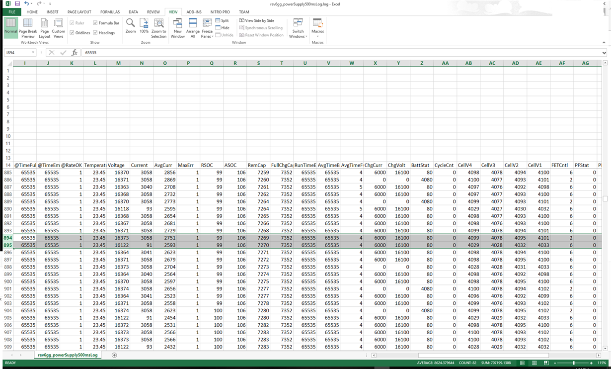
    Your latest log shows a continual charge vs COV, with the ~90mA when the charging stops. I see some odd data earlier, such as around line 896-899, where the current dropped from 3A to 93mA briefly, although FETControl shows both FETs are still on. Do you know what might cause this? Is this your voltage source or something with the device?
  • In entry 894, I see the FET go from 6->2.  Then entry 895 have a current reading of 91mA. 

    We are using a regular power supply and are not doing anything abnormal (as far as I know). (Leader 790-3D, 30V 3A supply.)

  • Sorry, I think my line numbers don't quite match up with yours, after I pulled the file into xls. I was referring to the timestamp 2:46:30-31 range, there are 3 readings with low current and FETControl=6.
  • It seems like your voltage source is running right near its 3A limit, is it possible it's doing something odd because of being right at the limit?

    When you start the log, the current is reading zero, it only seems to start the 90mA readings after the first COV triggers. Did you issue a reset to the gauge before starting the log, after the previous experiment left it in PF? Or the only commands you send is to unseal and clear the PF?

    If you can rerun the log, you might try a charge with a much lower charging current, to see if it only occurs with a current above X-mA, doesn't occur with a current below that threshold. Given the pack is already fully charged, it should still be possible to overcharge and trigger COV with a low charging current. I'm guessing that the COV is somehow triggering the current measurement error, so I'd like to trigger it with as gentle manner as possible.
  • I will re-run the test at a lower current and get back to you.

  • And I did not answer your question. The pack is already un-sealed. We clear the PF, and then reset it.
  • Terry, is there something else that we can do? The slow response time due to the nature of support forums is really killing us over here. We halted production which means we lose revenue. We also have angry customers asking for updates. Every second they are not using our batteries they could be evaluating other brands, etc.

    I am currently running your lower current test, but just trying to be keen with both mine and your time.

    1. Can we elevate this issue so that we can get faster response times and resolve this issue?

    2. What else can I be doing so that I do not have to wait for the next set of instructions?

    3. Is there any way that your team can setup one of your demo boards with our protection settings and share results to expedite this? Do you want me to overnight a battery to you? In short, we need this to go faster. Let me know what you need.
  • Hi David,

    I understand your position, and I wish we could have already identified the cause and be moving onto a fix by now.  I've been pulling in several of my colleagues as well for consultation, but we haven't found anything obviously wrong thus far.

    How many packs do you have that exhibit this issue?  Do you have a rough idea statistically how many of your packs are showing this?  Can you collect the IC marking from all problem packs, so we can see if it may be correlated to a certain device lot?

    If you have multiple problem packs that you can reproduce the issue on, it may make sense to ship up one, if it will be straightforward for us to connect to it and communicate with it.  You'd mentioned having a custom board to facilitate SMBus comms when the FETs are off, do we need that as well?

    Thanks,

    Terry

  • Hi Mike,

    Sorry I didn't respond to this yesterday - we can view a variety of formats, including gerber, pads, altium, plus there's always pdf.

    Given that not all your packs are showing this issue, plus it seems to recover after clearing the PF and reset, I would not suspect a layout issue as the likely cause. However, you can send it anyway, in case it may be useful for reference.

    Thanks,

    Terry
  • I can ship you everything that you would need.

    You stated above that not all batteries are exhibiting the behavior. We do not know that. It seems that they fail pretty regularly when using a certain charger. And we can get any pack to fail using the power supply easily. All you need to do is turn the supply on at 17.2V @ 3A and wait.

    We have had about 20/2000 fail. But unfortunately, the failures happened to a very important customer and they need clarity to what is going on.

    You mentioned that you have pulled several of your colleagues into a room for consultation; are they still actively working on this issue? If not, how can we get this elevated so we can resolve this?

    Additionally, is there any other thing that I can do while we wait? It has been 3 days so far, and I have no update other than I can get it to fail on a power supply. I had assumed that if you can re-create it easily, one should find the solution. Was anyone able to re-create the issue using one of your demo boards?
  • Ah, so I misunderstood that from the earlier discussion, I was under the impression it was not 100% fail. We can tackle that differently, let me see what we can reproduce on our side separately.
  • Hi David,

    It took awhile, but we did manage to reproduce something similar on an EVM by this evening. We have captured logs from that, will continue to do additional experiments tomorrow. What we're seeing is a little different than your case, so we have to figure out what is causing that, then see if that also explains your case.

    Did you uncover anything further from your own experiments?

    Thanks,

    Terry
  • Terry,

    We currently have 3 experiments going on:

    1. We are currently running a lower current test with a failed battery that you had asked for. It has run since yesterday without failure. (17.2V @ 1A)

    2. We are trying to capture the failure on our charger. We have the logger running, but of course the battery will not fail with the test equipment on it.

    3. We have a test where the second level parameters were adjusted to a higher voltage. The power supply is set to 17.2V @3A. This test has not failed yet. This was testing a band-aid if root cause could not be found. We do not want to increase the voltage because the capacity will increase, competitor chargers would charge the battery higher, agency markings would be wrong, etc.
  • Terry,

    Do you have an update from your team? Is there a timeline? I need to give an update on my side.

    -Dave
  • Terry

    We ran a test over the weekend with the following setup:

    - 2 batteries sitting on a charger that originally caused this failure (prior to Jervis re-creating on power supply)

    - logging every 2 seconds w/ the BQ software

    - logging every 2 seconds the current across the sense resistor with opamp circuits.

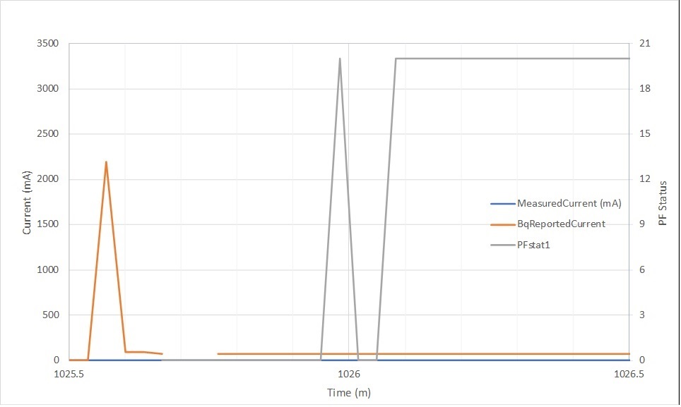
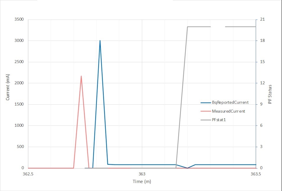
    The purpose of this test was to validate what an external circuit is reading in comparison to what the Bq is reading.  One would think that if the BQ part is measuring a current above x milliamps for > 20 seconds, then another should measuring the same points should capture the same thing.  

    Both packs went into the CFETF perm failure, one after about 6 hours and the other after 17 hours.  Below are the graphs with the comparison.   At the time of the CFETF failure, the BQ's measured current did not drop down to ~0mA (it was about 80mA of Charge Current) while the Opamp (diff amp) measured roughly 1.7mA.  Please see below:

    Thanks,

    Mike

  • Terry,

    Could you please provide an update?  You have not responded in a couple of days and I need to get an update.

    -Dave

  • Hi David,

    I'm out of the office myself, but my colleagues are still working on it, I'll let them respond directly.

    Thanks,

    Terry

  • Thank you Terry!
  • David,

    I've been working with Terry on this. We managed to reproduce and log something similar when using Ke24xxs are src/load. We have sent the logs to our firmware engineers to show the issue and they are looking at it now. We will update this thread when we have their replies.
  • Batt/Terry,

    Is it possible to get daily updates?  These updates do not have to be through this forum.

    1. Where are we now?  

    2. Who is doing what, and by when?

    3. What is the timeline?

    4. What should we be doing?

    This product is only a couple of weeks old and we have halted production.  No production, means no revenue.  There are many pieces in this puzzle and everyone is asking questions and I end up giving updates like "TI is working on it."  As you can imagine, some are not happy with this update.  Does this make sense?  Is it possible to answer my questions?

  • 1. We have fw engineers working on this problem.
    2. At least one engineer has been directly assigned to this issue to look at the code. We have provided him with our debug logs
    3. We do not know for certain but we will do our best to resolve it quickly as we understand your urgency.
    4. We can give you daily updates on this forum.

    We, as apps engineers are at a loss t explain why/how the chgfet is not turning off. That is the reason we are looking into the code. The fact that the error is resettable does not indicate hw failure. It might be a fw component that is misbehaving at voltages over 16.8V. We will do our best to keep you informed of our progress here. We are truly sorry that you are production stop. We will do our very best to resolve this for you quickly.
  • Batt,

    Thank you for your reply.  And thank you for understanding that we need to be kept in the loop. 

    Could it be possible to communicate rough some dates?  Is it a day, a week, a month, years?  I need to tell our team what we are expecting including our contract manufacturers, planning, etc.

    -Dave

  • Hi Dave,

    Though we can't give you an exact timeline to resolution, we don't expect it to be longer than a week. Yesterday and today we had a fw engineer inspect the code to see if some registers with data that would cause AFE actions to trip the fet were not being reported or written to correctly at high voltage. They also observed what apps saw, in that there is a leakage current when CHG in registers is off. We are still evaluating if this is hw or fw or a combination. To that end, we have also received programmed evms to test out conditions in which this result is seen. Please be assured that we will keep you updated every step of the way. You will receive the next update on this thread on Monday. The applications and fw managers are aware of your line down issue and therefore have dedicated resources to getting you back up quickly.
  • Batt,

    Dave it out of the office for the next few days, but I will be the contact on this thread.

    Thank you for the update.

    Jason

  • Batt/Terry

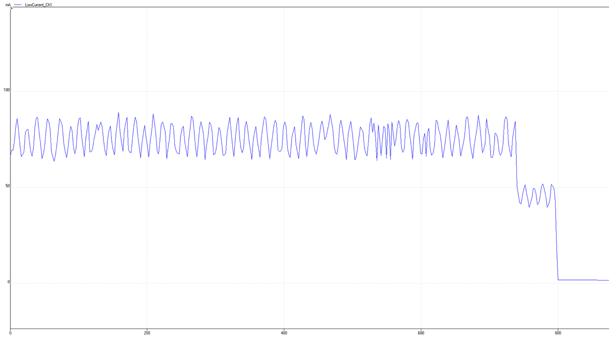
    Regarding the test data I sent in on 8/20, I setup another current measurement test.  Instead of measuring the current across the sense resistor directly (as I did with the data from 8/20), I measured much closer to the BQ part.  I did this in order to determine if any noise was getting picked up along the sense line that was causing some sort of false current reading.  This has been running for roughly a week all together, and the failure has not occurred.  However, we noticed something that I found interesting.  

    When we wrapped up the testing on 8/20, the packs were both in a CFET perm failure.  I took one of these packs and de-soldered the top of the battery pack from the PCBA (Batt +).  I de-soldered my opamp circuit across the sense resistor and soldered it to two components much closer to the BQ part.  Next I re-soldered the Batt + to power the pack back up.  In this process, I happened to have the logger running while I went to exit sealed access, clear the PF, and reset (0x0041).  During this time I was measuring ~80mA of charge current (sitting idle on my bench), which went away completely when the pack was finally cleared of all of the above.  See graph:

    At one point it dropped from roughly 80mA, down to just under 50mA.  I believe this happened when I exited sealed access mode, but it it could have been when I cleared the PF.  At the end, everything dropped back down to 0mA.  I found this interesting because there looks like there is current flowing at that time, I just can't determine the current path unless it is internal.  What is also interesting is that the 80mA wasn't shown at the end of the data from 8/20, so I'm not sure if something I did caused this or not.

    Let me know what you think of this data

    Thanks, Mike

  • Hi Mike,

    To clarify, is this logger data obtained by reading the bq20z45 current value, or from equipment monitoring your external opamp circuit?

    Thanks,

    Terry
  • Terry

    It is from other equipment (Picologger). I couldn't do the BQ logger because I was trying to reset the PF from the first test. After everything was cleared, I turned on the BQ logger.

    Mike
  • Hi Mike,

    Ok, I am assuming your picologger is capturing the output of your opamp circuit, correct? Thus this then looks like a real signal on the board, not just the gauge reporting a fake value when the actual board-level current is zero.

    An 80mA reported current across the 5mOhm sense resistor would result from measuring a 400uV level. With your opamp moved closer to the gauge and now seeing this, it makes us think you might be getting some unexpected current injected on the gauge-side of the sense resistor filter network. The filter network has 100-Ohm resistors isolating it from the sense resistor, so a 4uA current across that filter R could also generate a 400uV level.

    If it was a consistent 4uA, then you would not have it change when you clear the PF and reset, so it seems somehow that these actions are triggering the change. When you are in PF and are measuring this current, do you still have the 17V charger voltage attached? If so, does it change the reading when you remove the charger voltage?

    If it is still attached, when you clear the PF and reset, I assume the CHG FET may turn back on, is that true? So that turn-on could be triggering something that leads to this current.

    Are you using a real battery pack in your experiments, or something generated from a supply? If from a supply, can you measure the current flowing from the supply into the board, as well as the current flowing from the charger into the board? Just to be sure there isn't a "real" 80mA flowing anywhere, that should be easy to measure (it may be harder to measure an extra 4uA, though).

    Thanks,

    Terry
  • Hi Mike,

    One question came up in looking back at this data - why was there not a 2A-3A measured current spike in the upper plot? Was this just a sampling issue with the equipment? Or was it maybe earlier in time than is shown in the plot?

    Thanks,

    Terry