This thread has been locked.

If you have a related question, please click the "Ask a related question" button in the top right corner. The newly created question will be automatically linked to this question.

UCD9244 external synchronization

Other Parts Discussed in Thread: UCD9244, UCD74120

Hi,

I have several questions about the UCD9244 configuration when aiming for an external synchronisation :

We would like to know if the FUSION setup we chose is correct :

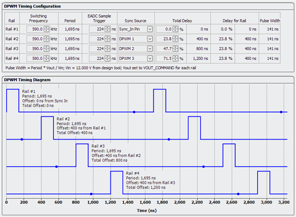
- All 4 PWM engines are by default defined to run at 590 KHZ.
- The signal applied to SYNC pin is a 625KHz clock because we want finally to run at 625 KHz.
- We want all 4 PWM engines to be synchronized by the external 625KHz clock.

The FUSION setup is the following :


- EADC was set to 423ns according to the formula.


QUESTIONS :

1) Is it correct to keep all the 4 "switching frequency" at 590KHz ? or should we define only rail1 at 590Khz and Rails2,3,4 at 625 KHz ?

2) Is it correct to change only the EADC for rail 1, and keep the EADC of rails2,3,4 to the initial 224 ns value, or should we change EADC for all the 4 rails ?


MEASUREMENTS :

3) When looking at the PWM output I noticed that the PWM period was not constant although the input is very stable :

These 2 graphs are histograms of the measured period.
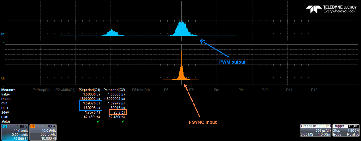


the 625Khz period exists (1.6ns) but also another discret distant from 4 ns.

==> Is this "normal" ? might this result from an inadequat FUSION setup ?


PRINCIPLE:

The default switching frequency was defined at 590 KHz. And therefore the CLA bank coeff calculated by FUSION are based upon this asumption.
However the effective switching rate applied is 625KHz, meaning that finaly the PWM is running at 625KHz with coeff valid for 590 KHz.
If we want the correct coeff to be applied, then we have to specify the Fsw freq to be 625Khz.
BUT in this case it is not possible to synchronize with the external signal since it MUST have a higher frequency.

Is there way to work around this problem ? May be by using 2 different projects ?

Thank you for your support,
Best regards,
Bruno

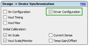
  • From my quick look at your configuration file, the EADC setting of 224ns should be the same between both the 625KHz and 590KHz frequency settings.  The Driver Configuration button was unchecked in the Design section of the Fusion GUI which was preventing the setting of the EADC value in the Configuration section from being updated.


    If there were a different EADC value between the two frequencies then I would use the higher of the two values for all the rails.

    You have the Sync Source chosen correctly but I'd set the Delay to the values for operating at 625KHz (400ns, 800ns, 1200ns).  This way it will be equally distribted when the sync signal is present, it won't be perfectly distributed at 590KHz but this should not affect operation.


    As for the difference in the clock frequency, if I'm reading this plot correctly, the difference between the highest and lowest values is 5.75ns (with the distance between the centers being ~4ns).  The clock that controlls the switching period runs at 250Mhz which would provide 4ns resolution, so I beleive this is the result of the Sync signal hitting the controller between adjacent clock cycles periodically.

  • Hi BRAD,

    Thank you for your reply..  But I must say I am a bit surprised by your proposals :

    1) Can you explain why you don't follow the datasheet (and SLUU490) recommendation when UCD is externally synchronized by Fsync ?

    It is written that in such a case, EADC should be modified to  EADC=1/Fsw -0.95/Fsync + 248 ns = 424 ns

    Then, should we keep 224ns everywhere , or 424 ns everywhere (rounded to 416) ?

    2) You mention that the "driver configuration" box was not checked and this is true.

      The real story is that this box was initialy checked in the project, but was automatically uncheked by the tool as soon as I changed the EADC value (fusion online modification) . DOes this make a difference since I did launch the "write to hardware" button ? ( and store to flash)

    3) The period offset from the graph  is exactly 4ns which corresponds to the 250MHz internal clock you mention. Apparently it is not possible to avoid that digital effect. Is it ?

    4) You did not answer to my question in "principle" paragraph. Please have you some advice here ?

    5) Note that the UCD9244/UCD74120 works fine for now, but I just want to be sure that the configuration I did is correct..

    With best regards,

    Bruno

  • Bruno,

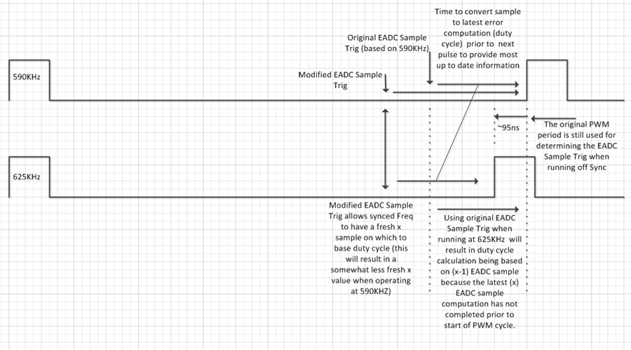
    1) Yes, you are right, I went from memory and my response was incorrect, you should be using the equation to calculate the EADC Sample Trig point.  This is because the sample point is still based on the pre-programmed frequency (590KHz).  If the same value of EADC Sample Trig is used at the synced frequency (625KHz) then the calculation of the latest duty cycle will not complete before the next PWM pulse.  It appears the designer of the equation erred on the conservative side when creating it, using the offset value of 248ns (larger than the range of  EADC sampletrig  values (224 to 240ns) and using 95% of the period for the synced frequency (possibly to account for a 5% tolerance on this incoming frequency) to determine the difference in time between the duty cycle pulses at the synced and un-synced frequencies.

    Hopefully, the following diagram helps clarify the equation.  The difference between the timing of the duty cycles is ~95ns but the equation will calculate out to ~175ns.  Then the worst case EADC sample trig of 248ns is added to this for a total of ~423ns.  This number should be used for all EADC Sample Trig values.

    2)  Ignore my comments on the Driver Config box this will become un-checked when the EADC Sample Trig value is manually updated.

    3)  The Sync In pin is sampled so the expectation is that the signal may hit the pin between adjacent clock cycles, there is no way around this.

    I will follow up shortly for the remainder of the questions.

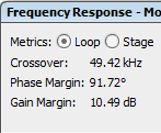
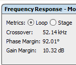
  • 4)  As long as the chosen compensation provides an acceptible response at both frequencies you are OK.  There is a negligible difference between 590KHz and 625Khz based on your file (you can perform this test by unchecking all the auto update component values in the schematic at the 590KHz frequency and then exit the schematic and update the frequency to 625KHz).

    590Khz

    625KHz

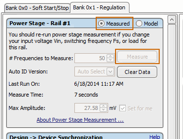
    5)  The loop modeling is reasonably close to the hardware but it doesn't take into account any parasitics and reflects the component values entered into the system.  It is always good practice to follow up with an loop response measurement (which is included with the Fusion GUI/controller - click the Measurement radio button and then the Measure button - button is grayed out in the image because I was offline)


  • Image wouldn't post at end of last reply.