This thread has been locked.

If you have a related question, please click the "Ask a related question" button in the top right corner. The newly created question will be automatically linked to this question.

PTD08D210W keeps shorting itself with low rail current. Need help with controller settings.

I'm trying to implement a system of TI controllers and drivers to generate upwards of 10 rails for a board design.  I needed accurate low-current measurements, so I added a sense resistor and instrumentation amp similar to a design on a Xilinx eval board.  When I adjust my current monitor gain/offset, and set my thresholds for current limit and fast current limit I'm running into issues.  The same PTD08 driver seems to get into some state where it burns itself out. The rail where this happens typically only draws a few hundred mA, so it's nowhere near the 10A limit for the part.  We must be doing something wrong in our settings.  I've killed 3 parts so far, so I'm looking for some help.  I've attached a PDF showing the power distribution architecture, and then the relevant pages of the schematic are also attached.  For some reason, U28 keeps killing itself and the VCC_POS_3P3V rail measure a low-resistance to GND.

PowerDistribution_r3.pdfPowerArchitecture.pdf 


  • Forward to digital power group.

  • Haven't quite figured out the root cause yet, but we have been able to get around the issue so far.  After reading the configuration data from a Xilinx eval board, we found that they were setting the fast current limit and over current limit up towards the upper end of the device range (10A).  We had our limit set much lower to match our expected current range.  Even though our current limits were set to a low value, we had our fault responses set to do nothing since we already knew there were no power distribution issues on the board.  For some reason with these low limits, the controller would throw faults and then the power module would heat up and break itself.  All of our rails were set to shut off on "power good" signals, so once the regulation was lost all of our rails shut off correctly.  I'm still not sure why the power modules were breaking, but we ended up just increasing our current limits greatly and setting a fault response to continue for 0ms when the OC limit was met.  Fast current limits are now being ignored.  We haven't seen any issues when configured this way.  Any insight would be helpful, but at least we have a working configuration for the time being.

  • Can you provide your original and updated configuration files for the digital power schematics that you included in the earlier post?

  • The problematic files have been modified and they weren't revision controlled, so at this point I only have our working version that doesn't seem to be causing issues.  I've attached the project files in a zip folder.  The problematic version was pretty close, but the Fast Over Current Fault Limits and Over Current Fault/Warn limits were previously set much lower.  Also, the fault response for these current limits was previously set to Continue without Interruption.  In the faulty design, we just had Stay On Dependencies between the rails that would shut down on power good indications from any other rail.  This might not be helpful without the original file set, but take a look and let me know if you see anything alarming with our configuration.  Thanks for your help!margining.zip

  • I did not see any issues with the configuration of the VCC_POS_3V3 rail from the provided project files that would result in the condition you have reported.  The output ripple was a bit high but this would not result in a observed failure.

    I have seen a couple other customers who experienced this type of failure and it was related to instability in the loop response that allowed the duty cycle to run at ~100% which will cause a failure in the device.  What I would suggst is to run a loop response test to see if the compensation is set correctly.  The modeling in the GUI is usually quite close to the actual response but it does not account for any parasitics and is heavily dependent on entering the design components that match well with the actual hardware.

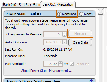
    The Fusion GUI/controller FW have the capability to run the loop response for you. Go to the Design page of the GUI and select the radio button for Measure rather than Model.  Then press the Measure button ( the button is grayed out in this image because I am working with an off-line project file, the loop response needs to be run on actual hardware).


  • Eric, did you get to the bottom of this?

    I am just bringing up a design using this same module, and I've found 14 out of 15 parts we placed are "failing" with 1 ohm shorts on the vout/gnd of each rail. We see this even on parts on a board that has never been powered on, but on the one powered board we find a high current draw and incorrect voltage regulation until the part elicits a fault flag - and on this part I see the low resistance on the output. The board has been checked for shorts and x-rayed. I'm positive there is no circuit error/layout issue causing this short. And indeed, removing the part showed the resistance followed the module NOT the PCB - the 1 ohm short is on the module output.

    Having researched a little, I saw other power modules failing with similar faults during reflow, and evidence seems to indicate this is happening to us too. So I'm wondering after reading your post whether your issue is not the loop response / configuration but actually a module failure. It looks like it's working but is sinking several amps through an internal "short"...