This thread has been locked.

If you have a related question, please click the "Ask a related question" button in the top right corner. The newly created question will be automatically linked to this question.

UCD 9248 programming through the PM bus

Other Parts Discussed in Thread: UCD9248, UCD9224

Hi All,

Good Day to you.

I am currenlty working on the UCD9248 device. I am trying to program the UCD9248 chip form my FPGA through SDA and SCL pins. I have few questions here, Could you please help me out in resloving the issues. Please correct me if i am wrong.

1. I do have a i2c protocol. and i am sending a word ( 32 bits of data ) to the slave ( UCD 9248) in a  SMBUS protocol,in the below format mentioned

start bit (1 bit)  slave address (7 bits) R/W (1 bit) ACK (1 bit) Command Code (8 bits) ACK(1 bit ) Data byte (8 bits)  (lower order LSB) ACK (1 bits) Data byte 2 (8 bits) (upper byte MSB) ACK (1 bit) stop (1 bit)  

Is the above mentioned format is correct ? if yes  question 2. if No could you please tell me the correct format to be sent..

2. I would like to configure the UCD9248 rail 1 VCCINT_0V9  Vout value,

    a. To configure the Vout value( VOUT_COMMAND) is there any basic commands or command code need to be set before setting the VOUT_COMMAND ? if no then question (b)

    b. To set the Vout value (VOUT_COMMAND) , what all the others parameters need to be set along with this ? could you please tell the other parameters and the sequence of the parameters need to be to UCD9248.

  • Hi Madeti,

    Q1: You are correct.

    Q2: If the UCD9248 is previously configured and you only want to adjust output voltage, only changing VOUT_COMMAND is enough. You may also want to change VOUT_OV_FAULT_LIMIT, VOUT_OV_WARN_LIMIT, VOUT_UV_WARN_LIMIT, VOUT_UV_FAULT_LIMIT, POWER_GOOD_ON, POWER_GOOD_OFF depending on your application requirement.

    Please refer to UCD92xx PMBus Command Reference. It can be found in Fusion GUI under Help.

    You can use Fusion GUI offline to configure your intended changes. Once you click "Write to Hardware" , the corresponding PMBus command will appear in the PMBus Log window.

    Thanks,

    Zhiyuan 

  • Hi Zhiyuan ,
    sorry for the delayed response. Thanks a lot for your inofrmation. I sucessfully implemented the requirement based on your inputs.
    I do have some more questions for you.
  • Hi Zhiyuan ,
    Sorry for the delayed response. Thanks a lot for your inofrmation. I sucessfully implemented the requirement based on your inputs.
    I do have some more questions for you. Could you please Help me out in resolving the below mentioned points.
    1. Currenlty i am trying to read the VOUT_COMMAND from the slave (UCD9248) in the below mentioned fomat.
    start bit (1 bit) slave address (7 bits) W (1 bit) ACK (1 bit) Command Code (8 bits) ACK(1 bit ) repeated start (1) address (7) Rd (1) Ack (1) Data byte low (8 bits) Ack(1) Data byte high (8) NACK (1)
    Is the above mentioned format is correct ? if yes question 2. if No could you please tell me the correct format to be sent..
    2. After i receive ack From the slave how many clock cycles will the slave (UCD 9248) takes to send the first bit of a byte (8 bits). To make it simple
    suppose if i receive the ACK at T1 time , will i start reciving the serial data at T2 time immedeately at the next clock cycle or will the slave take T1 + x time to send the data ?

    3. Also Can you please tell me the endiness of the serial data i receive from the slave. i.e will i get the bit 0 first or the bit 7 first of the single byte [7 : 0] from the sda pin (serial Data) .
    I will also let you know if i have some more questions for you.Thanks Regards,
    M.Pranesh
  • Hi Madeti,

    1. The format is correct. As to why host NACKs, you'll need to check the code in host.

    2. The first bit will be sent immediately at the following clock cycle. 

    3. The MSB (bit7) will be sent first.

    Thanks,

    Zhiyuan 

  • Hi Zhiyuan,

    Thanks a lot for the immediate reply. I need a just a clarification.

    1. As you said point number 1 "As to why host NACKs, you'll need to check the code in host". it means that in the code I need to wait for NACK until I receive the complete word and then exit . Am I correct ? that is my understanding.

    2. Currently I am trying to simulate / mimic the UCD 9248 . Could you please help me out in providing me a test bench in (Verilog or VHDL language) so that it will be easier for me to debug if any issues found on the Board. so I can quickly simulate and understand the behavior also , Similar way for which the micron company provides the models for DDR3 / DDR4 interface.

    Thanks Regards
    Pranesh
  • Hi Madeti,

    1. What I meant is that, host sent a read command, and UCD9248 returned data as required; now host NACKed and you want to know why. I was suggesting you need to debug host to find out the reason.

    2. I do not have the resource you asked. I don't know if it exists, probably not. The best way would be getting a UCD9248 on application board or a UCD9224 EVM. The PMBus implementations are the same.

    Please refer to PMBus specification 1.2, and UCD92xx PMBus Command Reference which can be downloaded from FUSION GUI under HELP.

    Fusion GUI has PMBus Log function. Whatever you configure through Fusion GUI, the corresponding PMBus commands will be shown in the PMBus Log window. Even if you don't have an EVM, the PMBus Log function still works. This would be another resource for you.

    Thanks,

    Zhiyuan   

  • Hi Zhiyuan,

    Thanks for the mail. I do have a quick question.

    1. I have done with the writing different voltage value to the UCD9248 and the UCD9248 slave is properly responding properlyt by chnaging the voltage value.

    2. But when reading the same voltage (READ WORD Protocol) i have followed the protocol mentioned in the documnet . and i am geeting som ejunk values from the slave which is not a;; related. and could you please provide m the timing diagram for the READ WORD protocol. so that i can cross check is there any timing voilation wrt to the specification.

    3. The problem i am facing is that is that i am directly putiing the code on the board without doing the basic sanity checkes, could you please try hard to get me simulation model of the UCD9248.

    4. Please kindly sene me the TIMING DIAGRAM for the READ WORD protocol. along wih the REPEATED START CONDITION. 

    5.  If host is sending the ACK bit to slave, is there any timing requirement for this condition. i mean once i receive the upper 8 bits from the slave i am not sending the ACK in the next cycle (T1 TIME) , i am sending the ACK AT t2 TIME . Will that cause any issue ? or should host send the ACK bit next cycle(TI Cycle ) immediate  after host has received the upper 8 bits completely.


  • Madeti,

    PMBus is a layer of protocol on top of SMBus. The basic timing diagram is in SMBus spec 2.0. It can be downloaded here:

    The read word timing diagram is in Section 5.5.5. The repeated start waveform is illustrated in I2C spec Section 3.1.5.

    The ACK must happen following the last bit of a byte. Otherwise it will be seen as a NACK. The related description is in I2C spec Section 3.1.6.

    If the host does not have enough processing time before the next clock, the host can hold the clock low until it is ready.

    Thanks,

    Zhiyuan 

  • Hi Zhiyuan,

    I have looked into the document which you have refered to me. And also my implementation is same as said by you. and i while going through the document i have found two things.

    1. Page no.76  B.5 REPEATED START Condition  

        "  As part of the SMBus protocols for reading data from a device the master generally uses a REPEATED START condition. See, for example, the READ WORD protocol in Section 6.5.5. REPEATED START conditions may not be understood by some I²C devices. An attempt to use a SMBus protocol with a repeated START condition to read data from an I²C device may yield unexpected results".

    Can you please elobrate the above statement ?

    2. i am currenlty implementing the READ WORD Protocol , I just want to understand what is meant my WORD in this context is it 32 bit or 16 bits ? If it is 32 bit then the READ WORD protocol mentioned in the SMBUS Specification documnet is only reading 2    8bits with an master/host  sending an ack,

    3. And also i feel that the slave is not probably detecteing my REPEATED START condition because when i see in the scope i found that there is a data coliision, i think slave is thinking for WRITE OPERTAION even though i intiated for READ operation, but i think it is sending ACK to host and host  may be seniding the ACK from.

    Not eexactly sure point no.3 as noticed from scope.

    and also i have gone though some other TI Documnet mentioned below. http://www.ti.com/lit/an/sloa132/sloa132.pdf 

    In that document it has been clearly written by telling how to read data multi byte Read, where there is no repeated start condition

    POTENTIALLY COMPATIBLE. Can you please help me out in reolving issues. I am not able to understand how come Write to the UCD9248 is working properly. With the same flow added repeated start why it is not working.  

  • Hi Madeti,

    My response is below:

    1. It means the repeated start condition may not be supported by I2C devices. UCD9248 supports PMBus 1.2, which is built on SMBus 2.0, therefore repeated start condition is supported by UCD9248. The paragraph you cited is irrelevant to the problem. BTW, the cited paragraph is from SMBus 3.0. You should read SMB2.0 instead.

    2. A Read Word command should return 2 8-bit bytes. Each byte should have an ACK. (SMBus2.0, page 31)

    3. Not sure what you meant. Please refer to SMBus2.0, page 31, Figure5-13. After the repeated-start, an address byte (with read bit) should be sent by host. Slave should ACK upon receiving its address, then it starts to send the first byte. Is this what you observed?

    4. The document you referred to is irrelevant. Your base material should be PMBus Spec 1.2. PMBus 1.2 cites SMBus 2.0 for the transport protocol and only describes the differences.

    Thanks,
    Zhiyuan
  •  Hi Zhiyuan,

    I have a few questions again i have gone through document which u have refered, and found that some data i am getting from the UCD9248.  So  few questions here. 

    1. I have currently set the FPGA voltage to 0.97V using the command code name as  VOUT_COMMAND with command code address as 8'h21, using SMBUS Protocol and the Voltage is set properly.Checked and verified . 
    Now if i want to read back the Volatge what i have set through SMBUS protocol from the slave (UCD9248) what is the Command Name and Command Code used ?

    I thought that it would be the same command code  (VOUT_COMMAND,  8'h21 ), is that True ? or should i need to send the the Command Code name as READ_VOLT with command code address as 8'b8B picked from page no. 100 , PM Bus spec 1.2 version .

    2. In the PM BUS document  page no. 85 section 18.4 says that  " If the VOUT_MODE is set for Linear or Direct format, the returned value is in volts. If the VOUT_MODE is set to VID format, then the returned value is the VID code corresponding to the voltage closest to the measured voltage". currenty i have not set any of the 3 modes through VOUT_MODE.. so what will be the Default Mode  ? ?

    3. Contuniation of Point no. 1, After i have set the FPGA voltage to 0.97V from the Texas Fusion Digital Designer , i have noticed in the Log file stating that " VOUT_COMMAND [0x21,Rail #1]: wrote 0.970 V [0x0F85] to RAM "  so now the Voltage value in hex corresponding to 0.97V  is 0x0F85. ? correct ?

    So assuming that READ_VOLT is correct for reading the output voltage,  when i executed the READ_WORD protocol with command code name as READ_VOLT,  i am getting 16 bits of data from UCD9248 as ( 0xBFF8).

           a.  Why i am getting the 16 Bits data ? i am supposed to get 12 bits of data ?
           b.  When loading through the Texas Fusion Digital Designer tool i am able to see only 12 bits (0x0F85) of data corresponding to the voltage (0.97V).

    Please kindly correct me if am wrong any were in the statement.

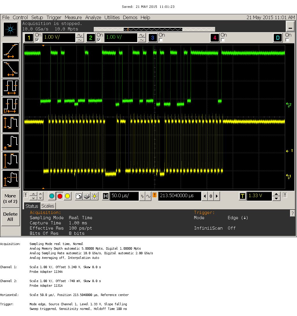
    also i have attached the snapshop of the scope for your reference, so that u can verify that i am following the READ_WORD protocol by senidn the Command code as 8Bh

    Thanks Regards,
    Pranesh

  • Hi Pranesh,

    1. To read back VOUT_COMMAND setting, use the same command code. READ_VOUT will read actual output voltage.

    2. Please refer to UCD92xx Digital PWM System Controller PMBus Command Reference, which can be find in Fusion GUI under Help. In UCD92xx, VOUT_MODE is fixed to linear format with exponent -12.

    3. Using exponent -12, we can calculate 0x0F85 is 0.97V, 0xBFF8 is 12V. So you are reading input voltage. Did you send READ_VIN (88h) instead of READ_VOUT (8Bh)?

    The waveform you attached is NOT 8Bh. It is sending 21h VOUT_COMMAND. The host NACKed the slave during transaction so the slave aborted. Please check why host NACK. Note that host must support clock stretching per PMBus 1.2.

    Thanks,

    Zhiyuan

  • Hi Zhiyuan,

    Thanks a lot this is a really ggod info.

    1. I just went through the documnent http://www.ti.com/lit/ug/sluu337/sluu337.pdf  page 3 , 2.1 section i understood most of the part except one thing " X is the signed 5 bit two's complement binary integer exponent from VOUT_MODE" , If u can explaing me with an example it would be really help ful to me.

    I know one  method,  suppose if i set 0.907V  to FPGA in the calculation of  exp -12 format is  0.907 * 2 ^ 12 = 0x0F85. Is this correct ?  and the above statement and mentioned calucatiosn are havinng same meaning ? ?

    2. You are right sorry i sent a wrong screen shot.which is sending 8'h21 only instead of 8'h8B.

    3. You have not answered my question no 3a and 3b .from previous converstaion.

    And one more thing i have forgot to tell you, that in my design i am hving the scl as ouput  not as inout .... so any problem you find ?

    I will check and let you know if any problems i face.. and mean while i will also think if i have any doiubts to ask you.

    Thanks Reagrds

    Pranesh


  • 1. Please refer to PMBus 1.2 spec Section 8.2. It explains the VOUT_MODE command. In UCD92xx, VOUT_MODE is read only. The exponent is fixed to -12. Your calculation is correct. 0.97 * 2 ^ 12 = 0x0F85

    3. a. As I explained, the value you got is 12V. You were probably reading READ_VIN.

    3.b. As I explained, 0x0F85 is correct (0.97V).
  • Hi Zhiyuan,Thanks ..
    But coming to Point no . 3a i have cross checked my Code and found that i am Reading the VOUT_COMMAND 8'h21 only .and also i have done one more thing, i have changed the Command code to 8'h8B (READ_VOUT) and chceked now. and found that i am getting complete 16 Bit data.
    so only asked you. and Tommrrow i will send you again the snap shot of scope. so that u can tell me if i am wrong.
  • Hi Zhiyuan,

    Good Day to you.

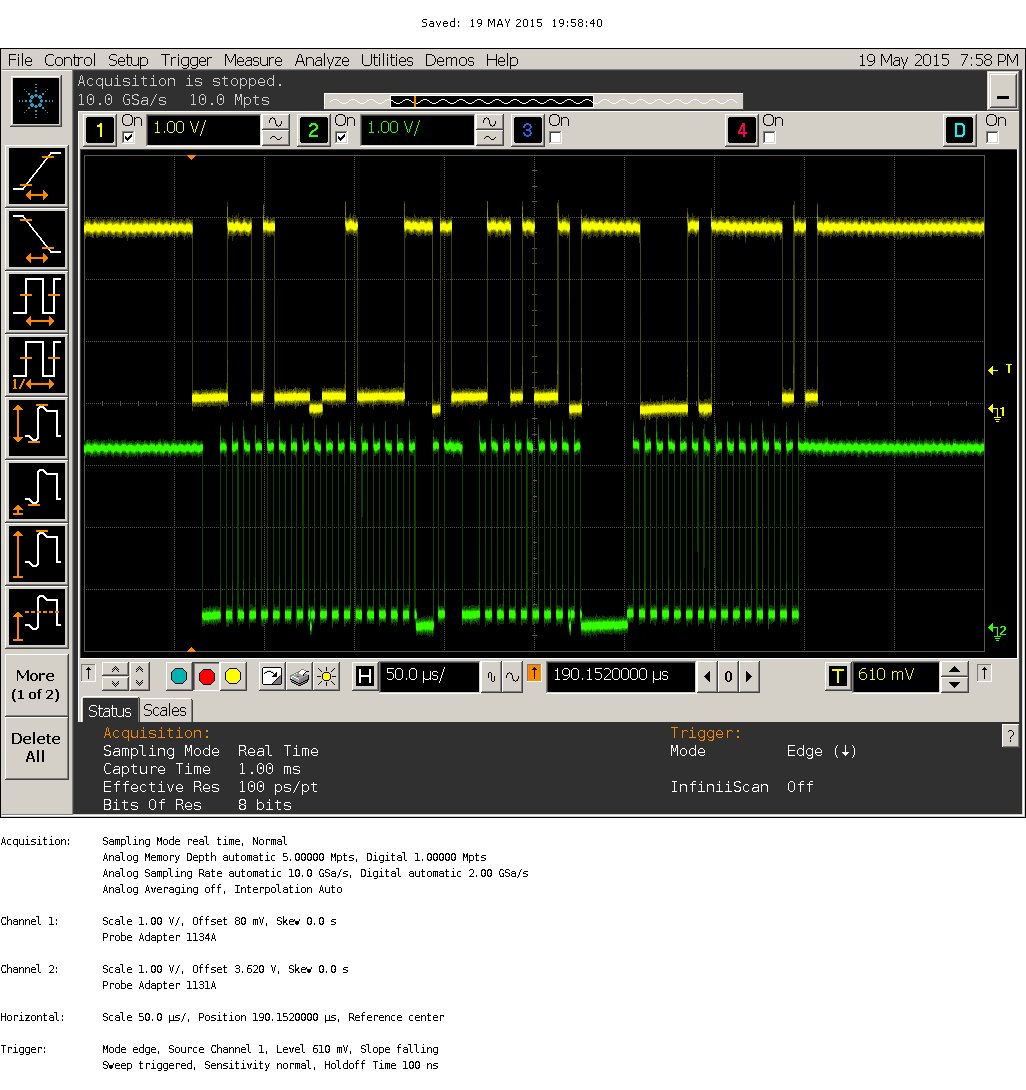
    As you said i have checkd my Code and verfied that i am sendind the Proper Slave Address and Command Code i am sending is 8'h21 attached the snippet . and also i have taken the snap shot of tehy scope.

    I am capturing the data in the below mentioned fomat.

    1. Data Lower Byte { 7 6 5 4 3 2 1 0}

    2. ACK From HOST

    3. Data Upper Byte { 15 14 13 12 11 10 9 8}

    Is the Capturing format correct ?

    I am getting currently 0xFF99  Value from the slave , with the Command Code as 8'h21. 

    If i am wrong please correct me. I am currenlty reading the VOUT_COMMAND.


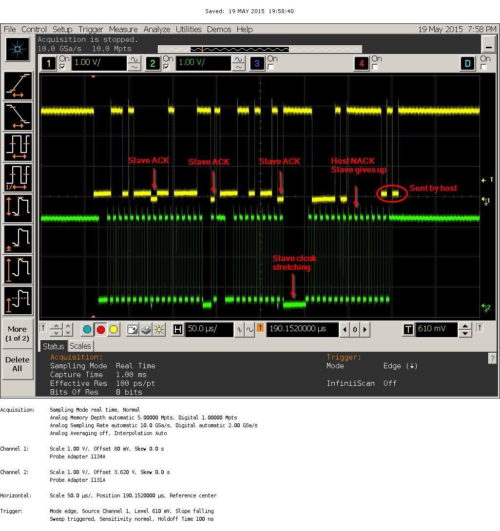
  • What I read from the waveform is:

    S 0110 1000 A 00100001A

    Sr 0110 1001 A 0110 0010 N 1111 1110 P

    The problem happens when host NACKed the first byte, then the slave gave up. The second byte is sent by host, not from the slave.

    Also, it look like 0 before the NACK is sent by host. You can tell it by observing "0"'s voltage level -- host doesn't pull all the way to ground, and slave pulls down to ground. The 0 before the NACK doesn't pull to ground, so probably slave wanted to send a 1 but host pulled low the data line and then NACKed the slave.

    You need to check what happened in host when receiving the first byte. Why does it NACK? Why does it pull the data line?

    Thanks,

    Zhiyuan